
The circuit''s connection point sits electrically between the two breakers, so that either breaker can connect it to its respective bus. Depending
The use of copper for the busbars to which these parts are connected therefore avoids contacts between dissimilar metals and the inherent jointing and corrosion problems associated with them.
Two generators rated 10 MVA, 13.2 KV and 15 MVA, 13.2 KV are connected in parallel to a bus bar. They feed supply to 2 motors of inputs 8 MVA and 12 MVA respectively.
Two generators G1 and G2 are connected in parallel to an 11 kV common busbar. The generator G1 is rated at 15 MVA, 11 kV with X = 0.10 pu and the generator
Two generators rated 10 MVA, 13.2 KV and 15 MVA, 13.2 KV are connected in parallel to a bus bar. They supply power to 2 motors with inputs of
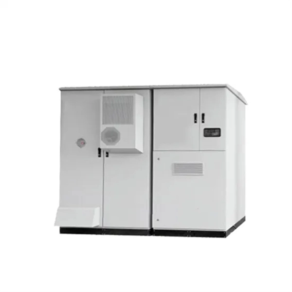
The unit has been factory-assembled and tested, offering standard connection points to protection and remote control circuits. This solution utilizes air-insulated busbars for connecting the different type of
In voltage differential busbar protection the CTs of all incoming and outgoing feeders are connected in series instead of connecting them in parallel.
These busbar systems are like standard products for a manufacturer and are not required to be custom-built for every application except for variations in ambient conditions or special site requirement like
The cross-connection of the two middle transformers to the upstream source ensures uninterrupted power supply to the eight-segment 10 kV busbar even if
The arrangement and connection of incoming and outgoing feeders in grid stations and substations and the number of busbars have a significant
2. Connection Isolator Q1 connects busbar 1, Q2 connects busbar 2 of the corresponding field to circuit breaker Q3. For the outgoing field, the connection to the outgoing feeders is established by means of
In extreme conditions, they may connect all feeders to a single bus, especially during a complete bus shutdown. Therefore, the selection of bus
This involved installing two transformers, with the 10 kV side employing a single bus segmented connection method. The advantages included simplified wiring, convenient operation, simple auto

PDF | On Oct 10, 2020, Rostan Rodrigues and others published Power loop busbars design and experimental validation of 1 kV, 5 kA Solid State Circuit Breaker
Why Parallel Operation of Transformers required By parallel operation we mean two or more transformers are connected to the same supply bus bars on the primary
1.00Scope: 1.1. This specification covers design, manufacture, assembly, testing before supply, inspection, packing and delivery of metal clad partitioned,SF6 gas insulated switchgear confirming to
This solution utilizes air-insulated busbars for connecting the different type of units together to achieve the requested substation layout solution and functionality.
The selected 110/10 kV Olympic substation, for the pilot implementation of a centralized digital PAC system, contains two power

The current approach for 110 kV substations primarily utilizes single bus segmented connection on the power side, with four transformers each connected to different buses (where the two middle
A parallel operation of the existing and the new busbar protection is very complex and involves many provisional steps (risks of false tripping). For this reason, the necessary deactivation of the busbar
This document describes and compares different types of busbar arrangements for electrical substations, including: - Single bus and single busbar with
Connecting the two middle transformers on the 110 kV side to different source busbars is very helpful. If one 110 kV busbar loses power, the eight 10 kV busbar sections still get their load supply.
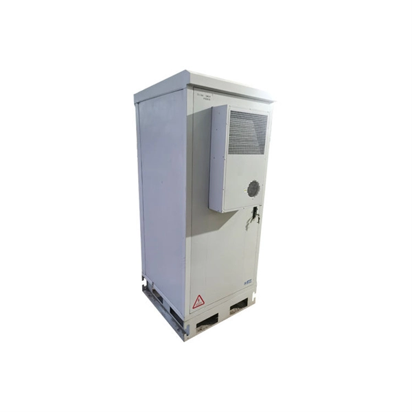
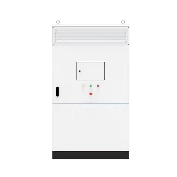
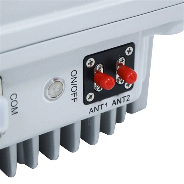
Contact us for competitive quotes on any of our power communication and smart grid products
Get a Quote