
Electromechanical protective relays operate by either, or. Unlike switching type electromechanical with fixed and usually ill-defined operating voltage thresholds and operating times, protective relays have well-established, selectable, and adjustable time and current (or other operating parameter) operating characteristics. Protection relays may use arrays of, shaded-pole, magnets, operating and restraint coils, solenoid-type operators, telephone-relay contacts.
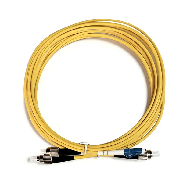
Fiber cable can be very flexible, but traditional fiber's loss increases greatly if the fiber is bent with a radius smaller than around 30 mm. This creates a problem when the cable is bent around corners. Bendable fibers, targeted toward easier installation in home environments, have been standardized as ITU-T. This type of fiber can be bent with a radius as low as 7.5 mm without adverse impact. Even more bendable fi.
Cable trays offer several key benefits: Easy Installation: Quick and easy to install. No special training or expertise is needed. Easy Maintenance: Since cables are visible, inspecting and repairing faults becomes easier. The flexible operation cable tray represents a revolutionary solution in cable management systems, designed to provide optimal protection and organization for various types of cables in dynamic environments. This innovative system combines durability with adaptability, featuring a unique. association representing the major electrical equipment manufac-turers in the U. The Cable Tray ng standards, performance standards, test standards and application in this document have been tested extens ompetent professional en completely installed, without damage either to conductors or. Setting up an efficient cable tray access path is crucial for ensuring that maintenance personnel can safely and effectively access and maintain electrical systems.
[PDF Version]
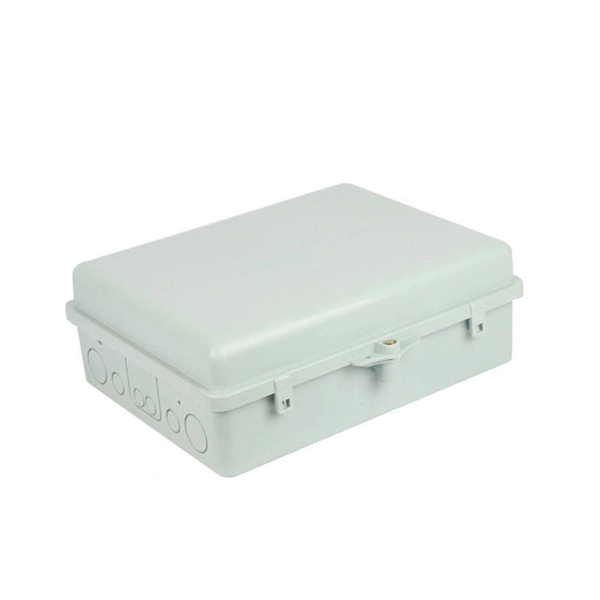
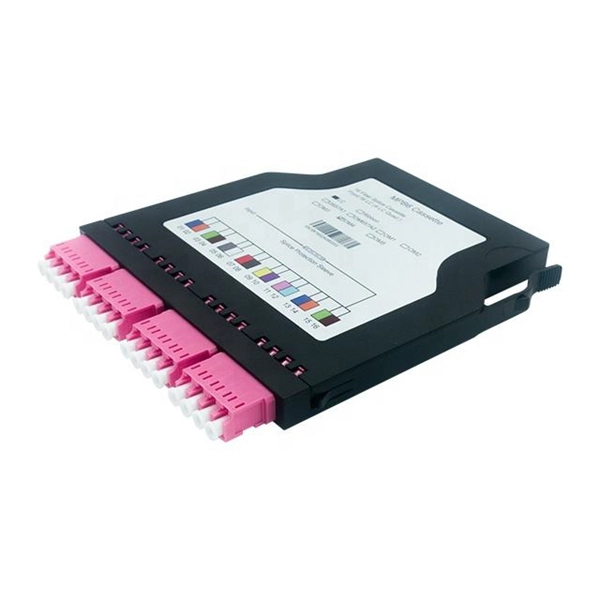
Fiber Termination Box, also known as FTB, typically consists of two main parts: the outer shell body and the adapter tray that protects the fiber connector points. It is a crucial component in fiber optic networks, primarily used for terminating, connecting, and managing fiber. What Is the Role of a Fiber Optic Terminal Box in FTTH? When most teams plan an FTTH rollout, they obsess over feeder routes, splitter ratios, and ONT models—but the handoff point where glass meets the living space is often under-specified. That handoff lives inside the Fiber Optic Terminal Box. Its primary function is to efficiently manage and terminate fiber optic cables, connecting the cable's core to a pigtail. It offers a cost-effective method to handle large quantities of fiber cables in an orderly. An Access Terminal Box is a protective enclosure used in fiber optic networks to house and organize fiber optic cables and splices. Even minor physical stress, such.
[PDF Version]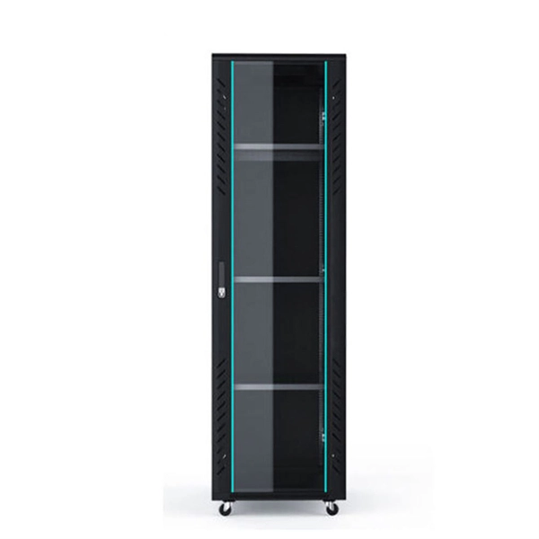
There are 8 steps to managing your network's security including: Be Organized. Develop and enforce a strong password policy. Ensure firewalls are properly configured. It implements security measures, policies, and tools that safeguard the entire network infrastructure to achieve the goal. This framework establishes best practices for device authentication, firmware updates, and real-time monitoring to detect potential threats. Develop data. This Security Requirements Guide (SRG) is published as a tool to improve the security of Department of Defense (DOD) information systems.
Cable sag results from incorrect spacing of cable tray supports or from employing the incorrect tray type that is, light-duty perforated trays in high-load applications. Complicating the problem are overloaded trays and large unsupported spans. Safety questions and cable damage can follow from this. Here are main approaches to either fix or stop drooping: 1. Materials and finishes available are mild steel pre galvanised as standard with mild steel hot dip galvanised after manufacture and stainless steel grade. B manufactures its cable tray in a range of materials with a variety of finishes. The selection of material and finish is a function of the environment in wh tant in a wide range of environments, and easily formable (Appendices II and III). Under. Is your cable tray system optimized for safety, dependability, space and cost savings? Cable tray (or cable ladder) systems are a popular alternative to electrical conduit systems, as they have an outstanding record for dependable service, design flexibility and cost savings in commercial and. OBO BETTERMANN has offered prod-ucts and solutions for electrical instal-lation for over 100 years.
[PDF Version]
The Trapeze or swing support is the most common type. Thread hex nut 25 mm (1") to 50 mm (2") above location of the tray bottom. The cross member comes next followed by a second set of square washers. All vertical hangers will project through the cross. This publication is intended as a practical guide for the proper and safe* installation of cable ladder systems, cable tray systems, channel support systems and associated supports. The following pages address the 2014 National Electrical Code® requirements for cable tray systems as well as design. The National Electrical Manufacturers Association (NEMA) Standards and guideline publications, of which the document herein is one, are developed through a voluntary Standards development process. This process brings together volunteers and/or seeks out the views of persons who have an interest in. We have more than a decade's worth of experience making and designing quality cable tray and cable management systems. Our knowledgeable production team works closely with each customer to provide quality solutions based on your schedule and budget.
[PDF Version]
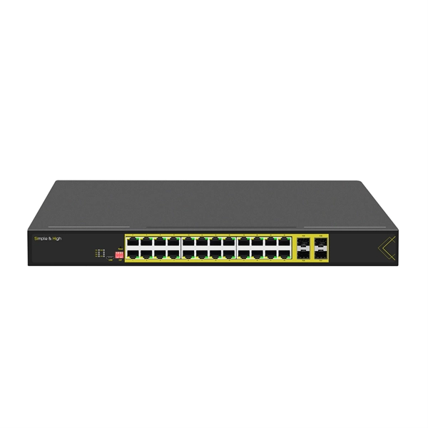
In order to configure 2 or more ports (up to 8) to be a port aggregate, simply navigate to Switching > Monitor > Switch ports and select the target ports, then choose "Aggregate". It is recommended that you do not have the target ports physically connected to anything during this. Port aggregation allows you to group multiple physical ports into one unit. Port aggregation is useful for implementing load balancing and provides a redundant link backup. Aggregating ports multiply the bandwidth and increase port flexibility for Sophos Switch.
A protective relay is an automatic device that detects abnormalities in an electrical circuit and closes its contacts. This action completes the circuit breaker 's trip coil circuit, causing the breaker to trip and disconnect the faulty section from the healthy circuit. Also principles of various protective relays and schemes including special protection. A protective relay is an intelligent electrical device designed to detect faults in power systems and initiate corrective actions such as tripping a circuit breaker. Its main purpose is to safeguard electrical equipment like transformers, generators, and transmission lines from damage due to. Combines protection, sensors, control power, and circuit breaker in a single package Typically added to a breaker close circuit to prevent accidental reclosure after a trip. Three fundamental components required for each circuit breaker. In other words, the prime function of protective relays is the timely and.
[PDF Version]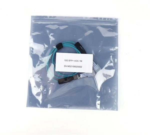
AN 835: PAM4 Signaling Fundamentals - This application note explains PAM4 theory and its operation. - 2019-03-12ed the high speed serial data industry to make a considerable shift in approach. Simple, baseband, NRZ (non-return to zero) signal modulation techniques are being left behin rate in half by transmitting two bits in each symbol, as indicated by Figure 1. We distinguish the PAM4 bit rate from its. ery aspect of our daily lives. We have come to take for. In this example, we use INTERCONNECT solutions to study the 4-Pulse Amplitude Modulation (PAM) format. The simulation can be set up from a new simulation, starting at. ded within the MP1900A Signal Quality Analyzer-R Op ation Manual. Ensure that you clearly understand the meanings of the symbols BEFORE using the equipment.
Contact us for competitive quotes on any of our power communication and smart grid products
Get a Quote