
To solder the wires to the relay, tin the end of the required wire, and bend the tinned end of wire in the middle with needle nose pliers to form a "U" shape. Please refer to them during installation in order to avoid problems. The protective measures used will determine suitability for automatic soldering or automatic cleaning. Please follow the recommendations. As electronic devices become more compact, it is becoming a common practice to weld the relay to a PC board (along with the semiconductors) rather than using plug-in relays with sockets. When relays are welded, their functionality may be affected due to seepage of flux into the relay. Where to find. In this guide, I'll walk you through pro-level soldering techniques, safety tips, and insights from real PCB assembly challenges.
Wiring Direction: Wiring between the main circuit breaker and each branch circuit breaker in the box generally goes on the left, and the wiring out of the distribution box generally goes on the right. Binding Requirements: The wires should be bound with plastic. Primary distribution systems consist of feeders that deliver power from distribution substations to distribution transformers. Many feeders leave substation in a concrete ducts and are routed to a nearby pole. At this. When a sizable plant expansion program is contemplated, modernization of the existing distribution system would be a necessary preparatory step. This document is not intended as a substitute for a detailed study or operational and site-specific development or schematic plan. Load factor, Coincidence factor, Contribution factor and Loss factor - Relationship between the Load factor and loss factor.
[PDF Version]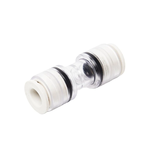
The SFP port is a built-in optical port of a Gigabit Ethernet switch, so it cannot be directly connected with a twisted pair or a jumper. It needs to be connected to an optical module first, and then it can be transmitted with an optical fiber patch cord. This project. This installation note provides the technical specifications and installation instructions for the Gigabit Ethernet Converters (GBICs) that you install in Catalyst 4000 or Catalyst 5000 series Gigabit Ethernet ports that accept GBICs. It uses a double-layer board design + minimal peripheral components to save costs to the maximum extent. In previous lesson, we had discussed about Ethernet (10 Mbps) and FastEthernet (100 Mbps) Straight-through and Cross-over. Ethernet is a family of specifications that governs a few different things: It covers all the different wiring specifications (10BASE-T, 100BASE-TX, 1000BASE-T, etc. ).
[PDF Version]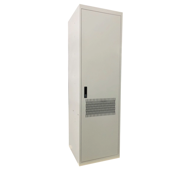
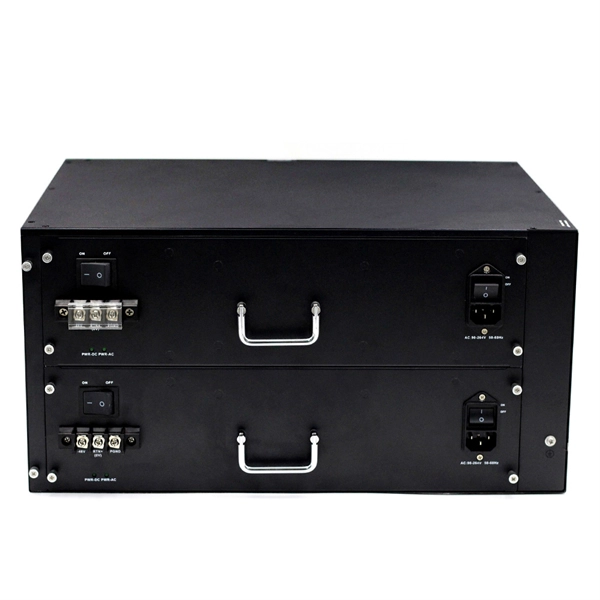
When multiple cables enter an electrical box, “pigtailing” is the preferred connection method. Pigtailing involves twisting the incoming hot, outgoing hot, and a short segment of matching wire (the pigtail) together with a wire nut. In this guide, we'll break down everything you need to know to install a distribution box correctly and confidently. Choose the right box based on environment (indoor/outdoor), load capacity, and durability. Check for proper IP/NEMA ratings and material quality. Wiring Direction: Wiring between the main circuit breaker and each branch circuit breaker in the box generally. This guide covers split load vs dual RCD vs RCBO board configurations, circuit arrangement and allocation, BS 7671 labelling requirements, type testing under BS EN 61439, SPD installation, wiring best practice, and the common mistakes found during EICR inspections. A high-reliability LV panel does more.
[PDF Version]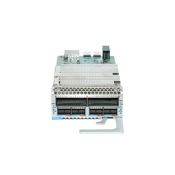
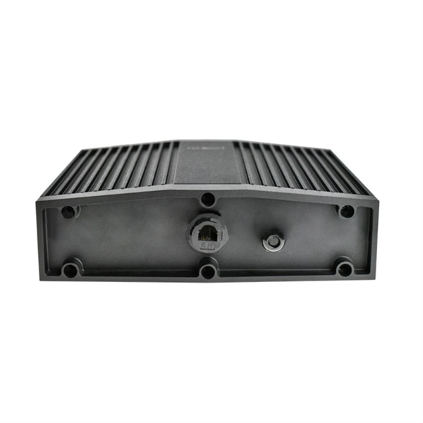
The shield is connected using a clamp or an EMC-safe cable gland (PG-gland) or other method that can ensure an efficient high frequency connection. The shield connection should cover as wide an area and have as low a resistance as possible. Never connect the shield to ground. Fig. 4: Optimal grounding with star-shaped structure The quality of a shield connection is reflected in. Protective Earthing is a requirement to divert unwanted, potentially hazardous currents from all exposed metallic parts such as equipment chassis, racks, cabi-nets, cable trays, conduit, and patch panels for personnel safety reasons and to avoid potential damage to equipment. However, the idea is always the same - electrical devices are not allowed to interfere with each other. The purpose of this presentation is to introduce some practical methods. This publication gives you general guidelines for installing an Allen-Bradley industrial automation system that may include programmable controllers, industrial computers, operator-interface terminals, display devices, and communication networks.
[PDF Version]
The process requires first to machine a dovetail ring hole and a countersunk hole in the lower and upper sheets, respectively, and then to inject a semi tubular rivet by compression through the lined-up holes to create a mechanical interlocking that can fix the two sheets in position. There are many situations where it is necessary to join two busbars to create a single, unified unit. Then we need to think about the fixing methods: All of these have many options and related pros and cons. As joints relax the resistance of that. One persistent belief is that copper busbar joints must fully overlap—matching the entire width of the bar—to ensure electrical safety and low temperature rise. However, real-world testing and. Abstract—The effect of design changes on the contact resistance of overlapping bolted/pad joints was investigated. 0 Jointing of Copper Busbars David Chapman 6.
Contact us for competitive quotes on any of our power communication and smart grid products
Get a Quote