
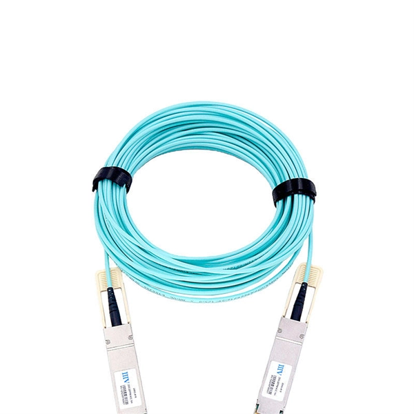
Testing a splitter or other passive fiber optic devices like switches is little different from testing a patchcord or cable plant using the two industry standard tests, OFSTP-14 for double-ended loss (connectors on both ends) or FOTP-171 for single-ended testing. First we should define what these. Splitter loss refers to the reduction in optical power that occurs when a single optical signal is divided among multiple output ports in a fiber optic network. Insertion loss testing of the optical splitter is very important to ensure compliance to the optical parameters of the manufactured. Optical splitters are vital components in fiber optic networks, distributing signals from a single input fiber to multiple output fibers. Here is a table of typical losses for splitters. Signal loss within a system is expressed using the decibel. The CertiFiber® Pro Optical Loss Test Set (OLTS) can be used to check that the loss of a PON Splitter (often referred to in various standards as a non-wavelength-selective or wavelength-selective branching device) to check that it is within the allowed defined limits. The CertiFiber® Pro has an.
[PDF Version]
The O2E is a high bandwidth, broadband optical to electrical converter available in a range of configurations. “Auto-Negotiating” is s pported on the copper interface side. According to different rates, encapsulation types and interface types, optical modules can be divided into different categories, one of which is the electrical port module. In the daily enterprise networking, compared with the. 45 Optical to Electrical Converters from 7 manufacturers listed on GoPhotonics Optical to Electrical Converter, also known as an optoelectronic converter, is an electronic device that converts optical signals into electrical signals.
Optical Flow uses a downward facing camera and a downward facing distance sensor for velocity estimation. It can be used to determine speed when navigating without GNSS — in buildings, undergr.
If the optical module is faulty, replace it with the spare part. If. Taking 10G SFP+/XFP optical module as an example, when the optical port of the optical module can not be UP when interconnecting with other devices, it can be troubleshooted from the following five aspects: The first step is to check whether the rate and duplex mode of the ports at both ends match. The following command shows how to enable the transmitting optical power alarm on port e8/1, set the maximum and minimum values, and clear the alarm thresholds. When troubleshooting potential causes: Determine if the downstream. 1) Unused protection: When an optical module is not in use, a dust cap must be installed to prevent dust from entering the port and causing poor contact. 2) Cleaning specification: Use special wiping paper or dust-free cotton swab to wipe the end face in the same direction.
They are fully-automated, full-color systems capable of high-accuracy measurements, automated defect detection, color verification, optical character recognition, and much more. Automated optical inspection (AOI) is a machine vision-based technology that uses high-resolution cameras and sophisticated image processing algorithms to inspect printed circuit boards for manufacturing defects. The system captures images of the PCB and compares them against a reference. Vario Line combines the best in fault detection, customer specificity and economic viability using 3D measurement technology and 2D image capturing. A new axis system based on. The optical module serves as a crucial component in optical fiber communication systems, operating at the physical layer, which is the lowest layer in the OSI model. Its primary function is to achieve optoelectronic conversion by converting electrical signals into optical signals and vice versa. Many different configurations are available, depending on the requirements of the.
[PDF Version]
The optical components primarily include: ITLA (Integrated Tunable Laser Assembly), CDM (Coherent Driver Modulator), ICR (Integrated Coherent Receiver). Coherent optical module is an advanced, typically hot-pluggable optical transceiver that utilizes coherent modulation (BPSK/QPSK/QAM) instead of amplitude modulation (RZ/NRZ/PAM4) for high-bandwidth data communication applications. After 2005, a technological breakthrough made coherent. Optical modules are key components in fiber-optic systems, converting electrical signals to optical signals to overcome signal loss and interference in traditional cables, ensuring efficient long-haul transmission. Wavelength and amplitude Phase modulation Tranverse polarization of light Electrical transmission of data has. detection (IM-DD), also known as on/ of keying (OOK) and non-return to zero (NRZ). While this modulation technique served the industry well, it became less ficient in terms of spectrum utilization as the data rate increased beyond 10Gb/s. It was also susceptible to fiber im on schemes like optical.
[PDF Version]Contact us for competitive quotes on any of our power communication and smart grid products
Get a Quote