
Use an optical power meter to measure the receive power of the port. Form a loop on the port using an optical fiber, and check whether the port can go Up (if optical modules with a long transmission
These mechanisms include the generation of loopback messages, measurements of packet delay or loss, etc. at the Ethernet layer which, in conjuction with the raw physical alarms provided by most
1.4.2 Example of Setting the OLT Optical-Module Alarm The following example shows how to enable the light transmission power alarm on port e0/1, set the minimum and maximum values, and clear the
By troubleshooting the PON system, network administrators can identify the root cause of problems and take the necessary steps to fix them, ensuring that the
Use an optical power meter to test the receive power of the port and check whether the optical fiber is disconnected. Use one optical fiber to form a loop on the port to check whether the port goes Up. If
When the receiving and transmitting optical power of the GPON optical module is not within the threshold, an optical power alarm will be generated. By configuring the GPON Uplink FEC
The document provides troubleshooting steps for FTTx GPON ONU issues. It discusses checking fiber connections and cleanliness if the LOS indicator blinks
If the transmit optical power is in the critical value, then replace the optical fiber and optical module as cross-checking, and if the receive optical power is in the critical value, then check

Go to the Monitoring > Logs pane to view the OLT logs from the PON Manager to check for any ONU-specific alarms. You can also check that the PON Controller docker logs directly into the Router.
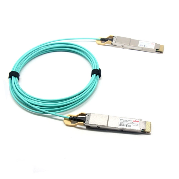
As core components of optical communication systems, the proper installation and use of optical modules directly impacts network stability. This article systematically identifies common
Passive Optical Networks (PON) have become a popular choice for broadband network access due to their high bandwidth, scalability, and cost-effectiveness.
Troubleshoot Troubleshooting Common Issues Cisco Catalyst PON Series OLT Troubleshooting Cisco Catalyst PON Series ONT Troubleshooting Troubleshooting Common Issues
Diagnosis method: add a register command to confirm whether the optical module emits a long light, confirm whether the board is calibrated, and
Troubleshooting a faulty passive optical point-to-multipoint network (PON) can be more complex than a point-to-point network. This application note looks at the use of non-intrusive or active fiber testing for
It is easy to trouble shoot the failure which occurs on a point-to-point FTTx network by using an optical time domain reflectometer (OTDR) test. However, troubleshooting a faulty point-to
Additionally, in PON networks, preventative measures are also essential to avoid network failures. For instance, FS ONU/ONT s utilize loop
What is the main advantage of using PON modules over traditional optical modules? PON modules operate passively, which means they don''t need
The PON Controller container isn''t running after the software upgrade or system reload Ensure that the pon-ctlr configuration is present using the show running-config pon-ctrl command.
ONU received optical power should be in range -8~-27dBm, and transmitted power should be in range 0~5dBm. After registering successfully, the PON process
The following command shows how to enable the transmitting optical power alarm on port e8/1, set the maximum and minimum values, and clear the alarm thresholds.
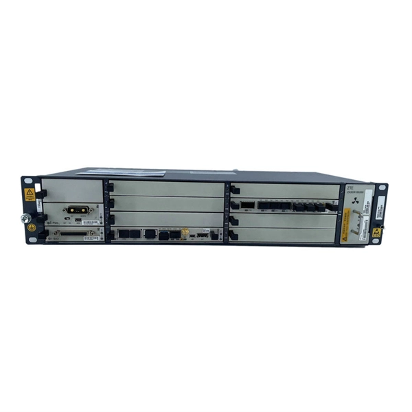
GPON System Optical Parameter Detection provides information about optical parameter diagnosis and the GPON port optical parameter threshold. It is mainly used to query the alarm monitoring of GPON
GPON Port Optical Threshold Alarm allows you to configure the GPON port to receive and send optical parameter alarm thresholds. When the receiving and transmitting optical power of the
Check the diagnostic information, which shows that the received optical power is low, with a threshold of -3 to -23.01, currently at -22.84. Once it exceeds the threshold, an alarm will be
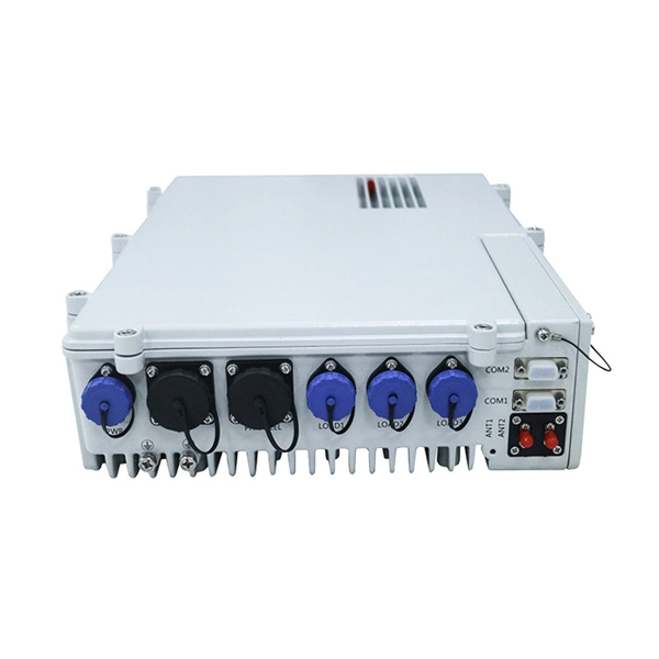
The parameters of optical module include the light transmission power, the light reception power, the temperature, the power-supply voltage and the bias current.
It provides troubleshooting steps for each alarm, such as checking connections, signal strength, and potential equipment failures. Additionally, it mentions specific conditions for both individual units (UN)
Alarm Object Alarm Name Alarm level Type of Alarm Possible Cause Possible resolution In case it is just a UN: optical fiber may be disconnected Check if the ONU''s PON port is connected to an optical
As per checked the log, it was found that the host port was disconnected, This alarm indicates the port and switch has been disconnected. Hence, we would advise you to perform cross

This article summarizes two common issues with optical modules and the corresponding solutions during the use of optical transceiver.
Contact us for competitive quotes on any of our power communication and smart grid products
Get a Quote