
Symptoms: Gradual increase in Bit Error Rate (BER), reduced optical power output (Tx), decreased receiver sensitivity (Rx), complete loss of light transmission or reception. Often causes intermittent issues before total failure. Interference can originate from neighboring cells, other electronic devices, or environmental factors, leading to reduced data rates, increased latency, and overall poor network. The results of this alarms was restarting of the RF unit. After combining the RRU log analysis and the alarm of the optical module, the radio frequency maintenance link is triggered by the power-off of the RRU board, as shown in the following screenshot. This type of test has been in use for 15 years or more within the OEM industry throughout the world. Monitor DOM/DDM Data: Utilize Digital Optical Monitoring (DOM) or. Intermodulation interference is generally caused by the fact that the Intermodulation signal transmitted by nearby radio equipment falls into the frequency band received by the TD-LTE base station.
[PDF Version]
To support the above-mentioned total cell tower build costs, Dgtl Infra references examples from some of the largest independent cell tower companies in the world, including American Tower, Crown Castle,.
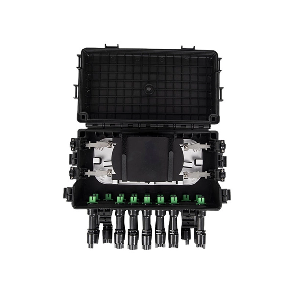
Step1 : Identify the optical cabinet and network operating center, and find the fiber optic splitter. Step 5: Patching from the splitter port to the user. Proper installation and regular maintenance of fiber optic patch cords play a crucial role in achieving optimized network performance, preventing signal errors, and extending service life. Fiber Optic Patch Panel Explaination Fiber optic patch panels are mostly mounted in 19 inch relay racks, but also on freestanding rails, cabinets. Correct patch-cord installation is essential for maintaining low insertion loss, stable return loss, and long-term reliability in both indoor and outdoor fiber networks. Whether you're connecting a data center, a corporate network, or a high-density fiber infrastructure, correct installation methods are essential.
The easiest way to update your firmware is to use the Delsys Software Update Tool for legacy sensors and base stations, or the Android Firmware Upgrade Tool for Bluetooth-enabled sensors. Below are the individual manuals that detail how to use these software to upgrade or. In case of any existing or perceived difference in contents between such versions and/or in print, the prevailing version of an ETSI deliverable is the one made publicly available in PDF format at www. Users of the present document should be aware that the document may be subject. This document provides a summary of software changes for the Faraday Update 1 Software release. Nuvation Energy BMS software releases have names along with version numbers. For example: Ampere -> Babbage -> Curie. LORD MicroStrain® is continually improving the functionality of its wireless nodes and base stations. Unplug the base stations from their power adapters, and then carefully unmount them. While. The update process takes about 3–10 minutes if done monthly or up to an hour if done every six months. A confirmation window will appear.
[PDF Version]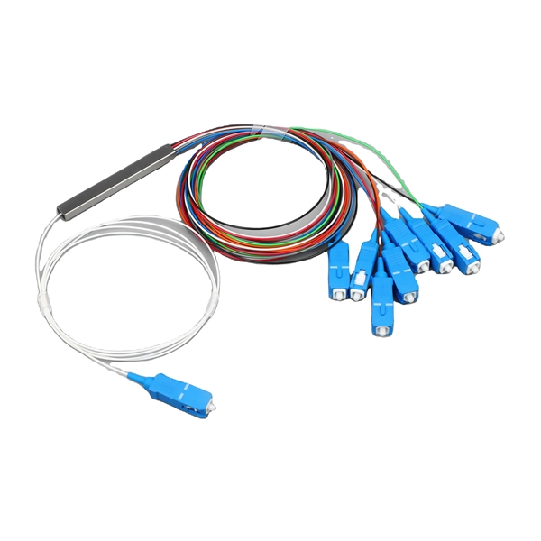
These Fibre Brackets help minimize interference and prevent damage or stress on the fibre entering the clip. They securely hold the fiber optic cable in place, preventing fibre from coming loose or shifting during use. Mounts and unmounts easily and quickly in a standard 19"". Essenta Components offer a comprehensive range of fiber optic holders, brackets and clips designed to keep fiber optic cables organized and secure. With a maintained minimum of a 2-inch bed radius, your fittings are made to better protect your cable from being bent or damaged. With four bulkhead FC input connectors, the Model 9096 gives you quick, convenient, and secure couplings between connectorized fibers. Features: Accepts 5/8" mounting hardware. Cleats to prevent bracket rotation on wood poles. Material Base: Ductile Iron, Hot Dip Galvanized Material End Fitting: Aluminum Material Rod: Fiberglass, gray ultraviolet. The FIBERLIGN Fiberglass Brackets are designed to support and mount various types of ADSS hardware when pole space is limited.
[PDF Version]
Complete IEC 62305 lightning protection guide covering risk assessment (Part 2), LPS classes I-IV, rolling sphere method, down conductors, air termination, and SPD selection. We offer a complete, integrated capability to provide lightning protection solutions for towers, antennas, and other structures. Our products can. – Lightning attraction effect and power supply mode of communication towers – Sensitivity of equipment – Economic benefits Definition and statistics of lightning strike intensity Thunderstorm Day Nk: Nk < 25 days – low risk area Nk > 25 days – medium risk area Nk > 40 days – high-risk area Nk > 90. This case study analyzes a 220 kV–400 kV substation connection using 36 power transmission towers, 2. With this in mind, LEC has created a solution which makes it easy to implement a complete lightning. Recommendation ITU-T K. The need of protection is obtained from the methodology contained in IEC 62305-2, which is used to determine the relevant lightning protection. Investing in proper lightning and surge protection for communications infrastructure can avoid these risks and disruptions.
[PDF Version]
In electric power distribution, a busbar (also bus bar) is a metallic strip or bar, typically housed inside switchgear, panel boards, and busway enclosures for local high current power distribution, transmission, or switching substations. They are also used to connect high voltage equipment at electrical switchyards, and low-voltage equipment in battery banks. They are generally uninsulated, and h. Design and placementThe busbar's material composition and cross-sectional size determine the maximum current it can safely carry. Busbars can have a cross-sectional area of as little as 10 square millimetres (0.016 sq in), but. • – Data transfer channel connecting parts of a computer• – Low resistance electrical conductor for high current transmission and distribution• – Modular approach t. • Elmore, Walter A. (1994). Protective Relaying Theory and Applications. Marcel Dekker.• Paschal, John (2000-10-01). Electrical Construction & Maintenanc.
[PDF Version]
Our engineer's guide helps you choose the right outdoor cable tray based on environment, load, and corrosion resistance. Select HDG, Aluminum, or FRP with confidence. An outdoor cable tray represents a sophisticated infrastructure solution designed to organize, protect, and route electrical cables in external environments. Installed on ceilings, walls, or floors, these trays ensure safe cable routing while protecting against.
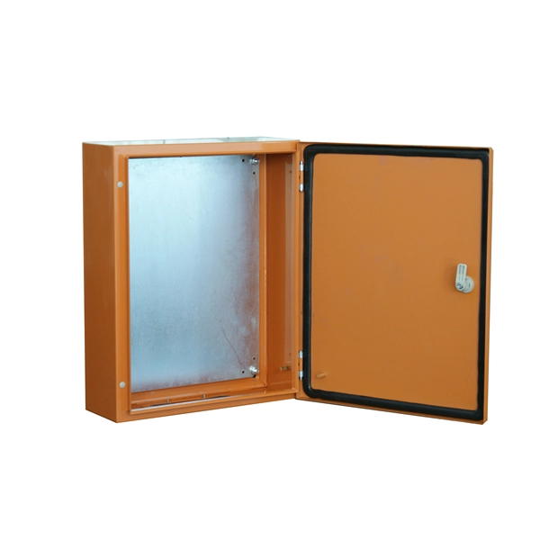
The distribution box allows the assembly of standard 18mm wide modules, on a DIN rail. Designed to be installed on a flat surface. Made in roABS plastic bust in. Box products are used to contain or enclose materials or equipment in a variety of contexts; plastic or metallic boxes suitable for constructing enclosures for electronic equipment such as guitar pedals, equipment cases for transporting tools or equipment, console style enclosures convenient for. Acrylonitrile Butadiene Styrene (ABS) Boxes Enclosures, Boxes, & Cases are available at Mouser Electronics. Choose from our selection of ABS plastic boxes, including corrosion-resistant washdown enclosures, compartmented boxes, and more. Compatible with the IEC60670-24 standard. It is equipped with a rubber seal that keeps the electrical components dry and effective in wet or harsh environments. High quality material: ABS plastic junction boxes are shockproof, heat.
[PDF Version]
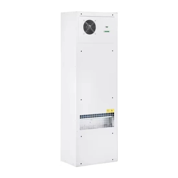
In the area of wireless computer networking, a base station is a radio receiver/transmitter that serves as the hub of the local wireless network, and may also be the gateway between a wired network and the wireless network. It typically consists of a low-power transmitter and.
Contact us for competitive quotes on any of our power communication and smart grid products
Get a Quote