
Conclusion LTE interference poses significant challenges to maintaining high-quality mobile connectivity. However, with advanced interference mitigation techniques and continuous
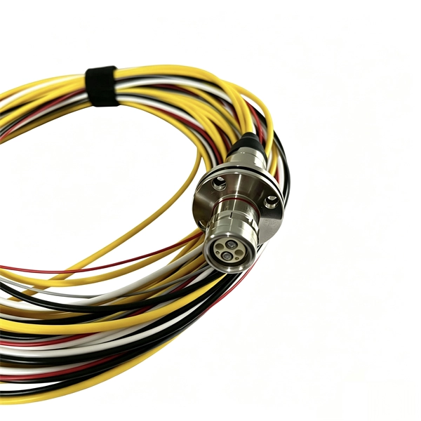
If none of these actions help, perform the following steps on site, until the issue is resolved: Procedure 1 Check the cables between the system module and radio module.
Inter-band interference: Interfering signals are generated out of the receive frequency band. However, the receiver receives out-o f-band signals
35 External Interferences Detection by Examples in LTE Networks for 4G and 5G Networks Efficient Deployments Eric Michel Deussom Djomadji
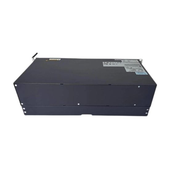
This document provides information about common 4G alarms, their causes, and troubleshooting steps. The 7100 alarm occurs when the RF module is not
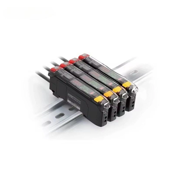
Base Station Alarm and Notification Handling Reference (GULI) - Free download as Excel Spreadsheet (.xls / .xlsx), PDF File (.pdf), Text File (.txt) or read online for
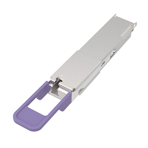
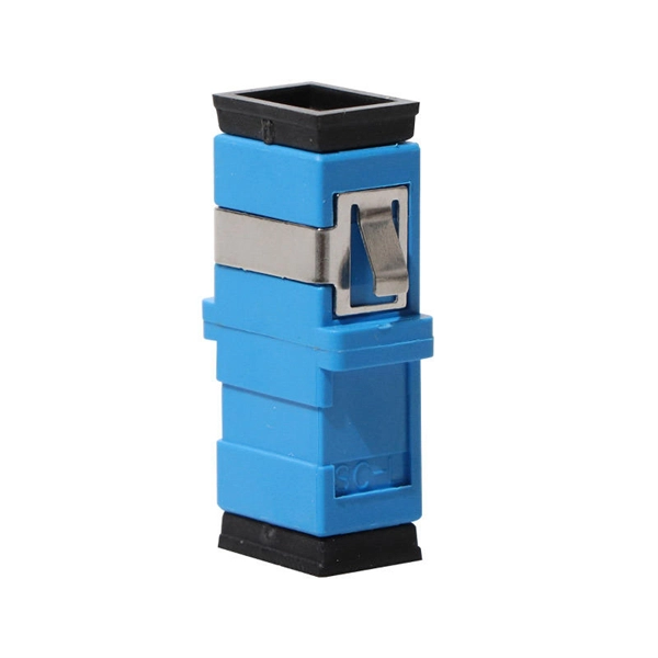
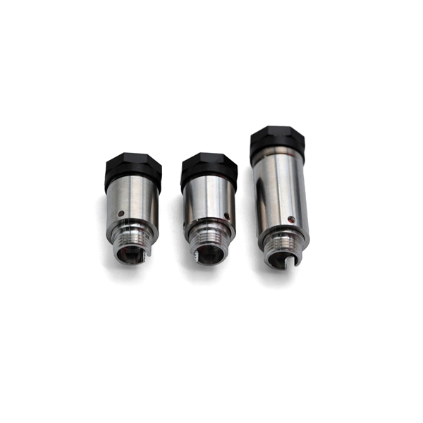
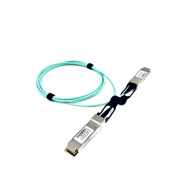
Optical modules in the application must have standardized operating methods, any irregular action may cause hidden damage or permanent failure.
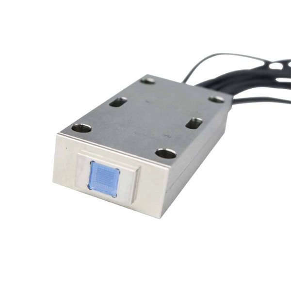
Overheating is a common fault in optical fiber modules that can be caused by excessive power, poor ventilation, or ambient temperature. Solution: To prevent overheating, it is important to
Also, interference regeneration and cancelation is mentioned and indicators of signal quality in LTE are named. In the end, a simple MATLAB simulation of the impact of interferences on the throughput is
However, one of the challenges in maintaining high-quality LTE performance is managing interference. This article explores what LTE interference is, how it affects mobile networks,
Care must be exercised because external interference devices can limit the quality of the testing. Antennas should be pointed facing clear sky with no metallic objects nearby.
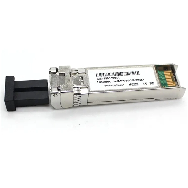
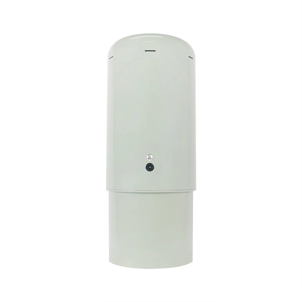
The low saturation light power caused by the multi-line and APD temperature characteristics is the two failure modes when the high-Speed
It describes techniques like RSSI analysis, frequency scanning, interference detection tests, and DTP testing to identify issues like passive intermodulation
After combining the RRU log analysis and the alarm of the optical module, the radio frequency maintenance link is triggered by the power-off of the RRU board, as shown in the following screenshot.
The local base station releases the UEs involved in the inter-base station handover procedure on the correlated X2 interface. Before the alarm is cleared, station cannot allow the inter-base station
However, identifying the root cause of interference is not so trivial; it requires engineers to diligently inspect all aspects of a base station, including internal and external sources, including co-located
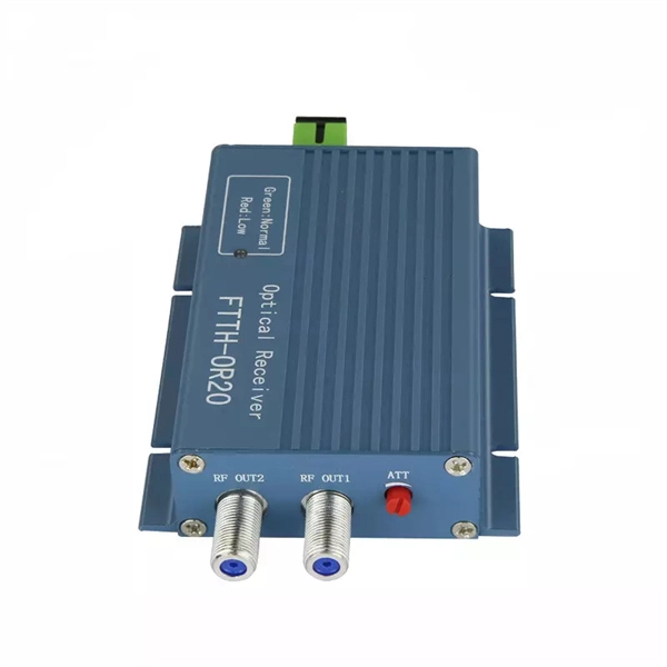
explores frequent optical transceiver issues and offers practical solutions, and highlight how LINK-PP optical module can mitigate risks.
LTE Signaling, Troubleshooting and Optimization is the Long Term Evolution successor to the previous Wiley books UMTS Signaling and UMTS Performance Measurement.
The document outlines troubleshooting principles for LTE FDD eNodeB, focusing on network management, hardware, and service issues. It details common
Explore common 5G NR physical layer test failures, their root causes like interference and weak signals, and practical solutions for optimization.
Second, with the explosive growth in the density and diversity of base station towers, we are seeing a whole new range of challenges caused by particular
Abstract We study the interference from a rotating shipborne radar system that spectrally and spatially coexists with a Long Term Evolution (LTE) cellular communications network in the 3.5
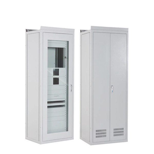
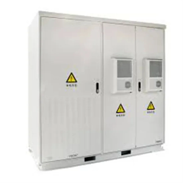
The interference analysis provides a technology support for electric power communication access network construction and late operation and lays the foundations for popularization and application of
This document contains descriptions for 43 service affecting alarms reported by a base station. The alarms relate to issues with baseband units, RF units,
In the first example, 1750 MHz is one of the third order products and falls within the AWS-1 base station receive band. If the 1940 MHz and 2130 MHz carrier sources are physically close to each other, or
Locating 4G LTE uplink interference Over the course of 2013, LBA has seen an increase in the demand for 4G LTE base station interference
The Problem: While not always the transceiver''s fault, the optical link loss exceeds the module''s budget. Causes include: Dirty or damaged
This document provides a troubleshooting guide for LTE RF channel faults. It describes common uplink and downlink channel faults such as uplink
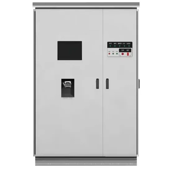
Contact us for competitive quotes on any of our power communication and smart grid products
Get a Quote