
Fiber optic cables are essential components in modern data transmission infrastructure. They support high-speed, interference-resistant communication and are particularly effective in applications that require high bandwidth, low latency, and strong signal integrity. Unlike traditional copper or. Minimizing signal interference is crucial to maintain the integrity and efficiency of these networks. This article explains what EMI is, how it occurs, and effective mitigation strategies like shielding, grounding, and filtering. In modern communication networks, signal. ITU-T has been active in the standardization of optical communications technology and the techniques for its optimal application within networks from the infancy of this industry. This manual attempts to. The Signal-to-Noise Ratio (SNR) is the single most critical metric in determining the performance and capacity of a communication channel, as defined by the seminal Shannon-Hartley Theorem: C = B × log₂ (1 + SNR) Where: C is the channel capacity in bits per second. B is the bandwidth of the channel.
[PDF Version]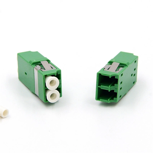
When multiple devices are connected to a split optical cable, there is a risk of interference and crosstalk between the signals. The distance over which an optical signal can be split is limited by the signal's. By dividing a single optical signal from a central Optical Line Terminal (OLT) into multiple outputs for Optical Network Terminals (ONTs) at users' homes, splitters eliminate the need for dedicated fibers to each residence—slashing infrastructure costs while scaling network reach. They are named by the number of inputs and outputs, so a splitter with one input and 2 outputs is a 1X2, and a PON splitter with one input and 32 outputs is a 1X32. Some PON splitters have two inputs so it. Unbalanced Power Distribution: Different output ports may have unequal optical power, leading to inconsistent performance of connected devices. Fiber optic splitters are vital components within.
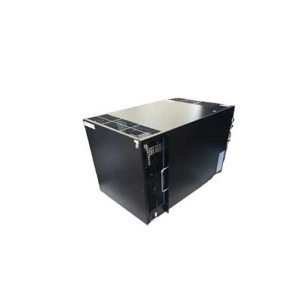
Symptoms: Gradual increase in Bit Error Rate (BER), reduced optical power output (Tx), decreased receiver sensitivity (Rx), complete loss of light transmission or reception. Often causes intermittent issues before total failure. Interference can originate from neighboring cells, other electronic devices, or environmental factors, leading to reduced data rates, increased latency, and overall poor network. The results of this alarms was restarting of the RF unit. After combining the RRU log analysis and the alarm of the optical module, the radio frequency maintenance link is triggered by the power-off of the RRU board, as shown in the following screenshot. This type of test has been in use for 15 years or more within the OEM industry throughout the world. Monitor DOM/DDM Data: Utilize Digital Optical Monitoring (DOM) or. Intermodulation interference is generally caused by the fact that the Intermodulation signal transmitted by nearby radio equipment falls into the frequency band received by the TD-LTE base station.
[PDF Version]Contact us for competitive quotes on any of our power communication and smart grid products
Get a Quote