
Calculate horizontal, vertical, or compound cable tray offsets based on bend angle, offset distance, and available installation space. This publication is intended as a practical guide for the proper and safe* installation of cable ladder systems, cable tray systems, channel support systems and associated supports. Part-2 Vertical Bend Tutorial. When offloading tray from a flat deck trailer using an overhead crane, care should be exercised in the placement and length of the slings to prevent crushing the product (siderails). This guide covers the critical steps, from selecting the right electrical cable tray and performing accurate cable fill. The bends, tees, crosses, risers and reducers of wire mesh cable tray can be easily and quickly made live at the project by using a bolt cutter. Since the jaws of the bolt cutter drags a layer of zinc across the cut end and forms a protective layer. Measure this distance along the straight tray.
[PDF Version]
If an EGC cable is installed in or on a cable tray, it should be bonded to each or alternate cable tray sections via grounding clamps (this is not required by the NEC® but it is a desirable practice). Cable tray may be used as the Equipment Grounding Conductor (EGC) in any installation where qualified persons will service the installed cable tray system. The design must comply with relevant regulations and standards.
The primary rulebook used in the safe use of cable trays is NEC Article 392. This is a description of how to select, install, and support these metal or plastic frames, on which electrical wires are installed. The purpose is to provide guidance for preparing accurate and complete electrical designs that are cost effective, energy. The Unified Facilities Criteria (UFC) system is prescribed by MIL-STD 3007 and provides planning, design, construction, sustainment, restoration, and modernization criteria, and applies to the Military Departments, the Defense Agencies, and the DoD Field Activities in accordance with USD (AT&L). This Specification is one ofa series prepared by Defence Estates (DE) an agency ofthe Ministryof Defence (MOD) primarilyfor usein its contracts for mechanical and electrical engineering works. The Specificationcovers electrical installations for buildingsother thandwellings. It is a revision ofthe. en completely installed, without damage either to conductors or structural system use maintain spacing or to keep cables in place when the tray is ect the minimum bend ra-dius for cables as they exit the bottom of the cable tray.
[PDF Version]
National Electrical Code (NEC) Article 392 (USA): This code provides comprehensive guidelines for cable trays, including requirements for cable types, fill capacity, support methods, and spacing., is a welded wire-mesh cable management system made of high-strength steel wire. The selection of material and finish is a function of the environment in wh tant in a wide range. us-trations without notice. Ensures tray stability and prevents stress on cables at turns. Prevents shifting, maintains order. Keeps cables tidy; may not be necessary. The International Electrotechnical Commission (IEC) is the leading global organization that prepares and publishes International Standards for all electrical, electronic and related technologies. Please make sure. In case of high power use, to meet the demand of currentAnd in order for the current to be carried at the demanded high powers to be met, the method of parallel connection of the cables can be selected.
[PDF Version]
The use and installation of cable trays is covered by legally enforceable OSHA regulations in 29 CFR 1910. In addition, this document contains several references to provisions of the National Electric Code. Scope: Firestopping for busway, cable trays, cables, and trunking passing through walls in enclosed electrical installations. Where cables pass through shafts, walls, slabs, or enter electrical panels or cabinets, openings shall be tightly sealed with firestopping materials in accordance with. Smoke poisoning is the cause of death of 95% of all victims of fire. To evacuate people safely from the building in case of fire, escape and rescue routes, as the central lifelines of the building, must always remain free of smoke and fire. To be able to guarantee this, there must be routes in. The MLAR deals with the installation of cable systems in buildings and specifies fire protection requirements for the laying of electrical cables.
[PDF Version]
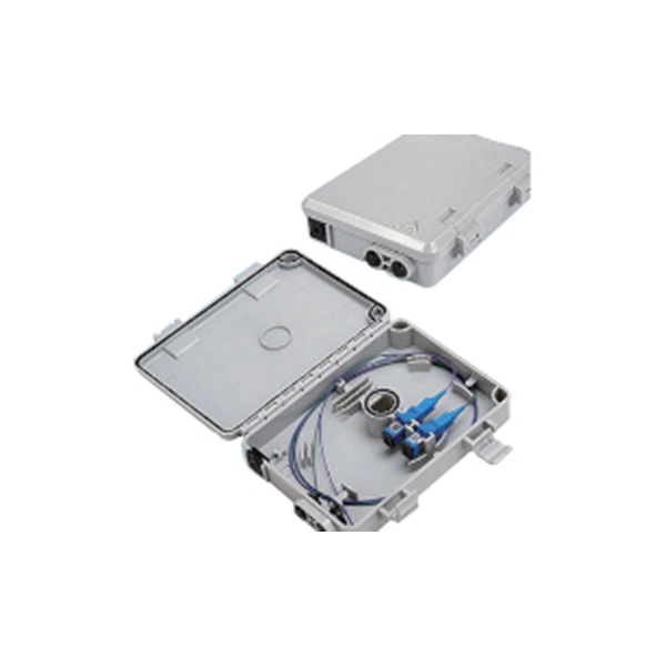
FRP/GRP cable trays by Middle East Fiberglass Industries L. – corrosion-resistant, lightweight, fire-retardant, and durable solutions for industrial, commercial, and marine cable management. West Port Cable Tray is recognized as one of the leading manufacturers and cable tray suppliers in UAE, specializing in premium cable management systems within the Middle East. Unlike traditional metal cable trays, GRP cable trays do not corrode, rust, or conduct electricity, making them an ideal. Middle East projects expose cable tray systems to extreme ambient temperatures, intense solar radiation, dust, and—often—coastal corrosion. MATERIAL FINISH: MS, GI Cable Trays, HDGAF, SS 304 Cable Trays, SS 316 Cable Trays, ALUMINIUM Cable Trays, GRP Cable Trays, WIRE MESH Cable Trays CABLE LADDERS.
Explore various cable tray types and sizes for electrical installations. Learn about ladder, perforated, solid-bottom, wire mesh, and channel trays in this complete guide. Each cable tray type performs a different function and comes in various materials such as aluminum. EAE cable trays and ladders provide high-strength cable protection that protects the cables from external factors. 6m can be produced upon request. Cable tray supports and. In practice, cable tray dimensions are a system of interrelated measurements —width, depth, length, and material thickness—that directly affect cable fill compliance, heat dissipation, structural loading, and long-term expandability. Wire Mesh Cable Tray. Cable tray (or cable ladder) systems are a popular alternative to electrical conduit systems, as they have an outstanding record for dependable service, design flexibility and cost savings in commercial and industrial applications. Because of its closed design, this type of tray should e used in applications where there is minimal risk of heat generation and buildup.
[PDF Version]Contact us for competitive quotes on any of our power communication and smart grid products
Get a Quote