
Cable racks and trays shall be closed by removable top covers, allowing adequate ventilation, in situations where: ‐ mechanical damage of the cables is likely to occur during plant maintenance
In accordance with its continuous impro-vement policy, Legrand reserves the right to change the specifications and illus-trations without notice. All illustrations, descriptions and technical information
Typical 300 volt insulated multiconductor instrumentation tray cables (ITC) and power limited tray cables (PLTC) cost the same for both cable tray and conduit wiring systems.
Learn about the importance of cable trays and pipes safety distances in ensuring system reliability. Explore standards,
Purchase UL 568. FG 1, Fiberglass Cable Tray Systems Covers construction and test requirements for continuous, complete nonmetallic systems of ladder, ventilated, solid bottom cable trays, or channel
Cable tray system shall be used for laying of MV and LV power, control, instrumentation and special cables in the Power Plant. Cable trays shall be
Attaching a channel cable tray by using the method illustrated in Figure 3-88 maintains the electrical requirements, and the bolted mechanical connection while providing a practical method for dropping
When installing two cable trays in parallel at the same height, the distance between them should be no less than 0.6 meters. This spacing is crucial for adequate maintenance access, ease of
A practical guide to product selection and installation This guide for engineers and installers has been developed by ABB as a practical reference regarding cable tray characteristics, installation, and
This article will explain the thermal and electromagnetic factors affecting cable ampacity in tray installations, discuss various calculation methods (analytical
Specifies requirements for metal cable trays and associated fittings designed for use in accordance with the rules of Canadian Electrical Code, Part I and the National Electrical Code®
Layered Separation: Strong current and high-voltage cables are positioned apart from low-current, low-voltage instrumentation cables. Layered separation
In cases where multiple cables need to be connected parallelly in the same phase; ensuring that the same current goes through all cables is possible by the right
A professional guide to installing electrical cable tray systems per NEC Article 392. Covers support, securing cables, and fill calculations.
The total load supported by the cable tray, uniformly distributed. This will be the combined weight of all of the cables or tray contents, any environmental loads (snow, ice, dust) and any concentrated static
Four different mesh cable tray types are available, depending on the requirements, area of application and cable quantity. The innovative Magic connection system of the GRM and G-GRM mesh cable
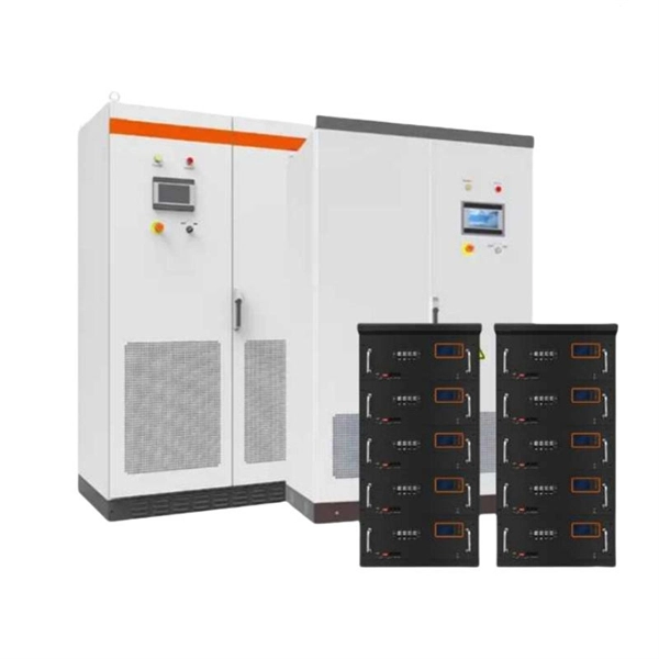
Cable Tray Cable trays are mechanical support systems that provide a rigid structural system for electrical cables, raceways, and insulated conductors used
4.1.2 The Metallic cable trays shall be manufactured in accordance with NEMA VE-1 standard and/or equivalent IEC standard. 4.1.3 Metallic cable trays shall be designed as a mechanical support for
FIELD TESTING35 Safety 35 Cable System Integrity 37 Low Potential Testing of Dielectric 37 High-Voltage Withstand Testing 39 Time-Leakage Test 41 POWER CABLE INSTALLATION GUIDE

Use standard three conductor cables with standard size EGCs and parallel the EGCs that are in the cable assemblies with the single conductor EGC (Sized as per Table 250-95) in the cable tray or with
This standards publication was developed by the NEMA Metal Cable Tray and Nonmetallic Cable Tray Sections. Section approval of the standard does not necessarily imply that all section members voted
Covers construction and test requirements for continuous, complete nonmetallic systems of ladder, ventilated, solid bottom cable trays, or channel type trays, intended for the support of power or

Do not use a cable tray as a walkway, ladder, or support for people; a cable tray is a mechanical support system for cables and raceways. Using cable trays as walkways can cause personal injury and can
Cable Tray Grounding: Power, Instrumentation, and Telecommunications Richard J. Buschart, Former Technical Director-Cable Tray Institute Grounding has always been a controversial topic. But, with
This document specifies requirements and tests for cable tray systems and cable ladder systems intended for the support and accommodation of cables and possibly other electrical equipment in
Explore the types of cable trays, their advantages, applications, and standard sizes. Learn how they improve cable management and support various industries.

Outdoor control cables may require larger conductor size to compensate for voltage drop due to the relatively long distance between the equipment and the control vault, especially for high-voltage and
A cable support system consists of cable support lengths and system components, such as cable support fittings, support elements, mounting elements and system acces-sories. The cable support
This guide covers the cable tray types and their appropriate applications, the fill rules for each configuration, ampacity derating requirements,
Contact us for competitive quotes on any of our power communication and smart grid products
Get a Quote