
To further understand how RS232 splitters work, it helps to refer to a good RS232 splitter circuit diagram. A typical circuit diagram will show the
A splitter can also be used to mix multiple audio signals into one output. In summary, RF splitters are essential components of any
Ethernet Cable Splitter Wiring Diagrams are essential when connecting multiple devices to the same Ethernet cable. With a basic understanding of how Ethernet
1. This circuit diagram shows an RS-422 splitter that splits a single RS-422 input into two isolated RS-422 outputs using an IC chip and resistors. 2.
Circuit diagrams for the resistor type splitter are shown below. The output of the 2-splitter has a 6 dB loss, and the output of the 3-splitter has an 8.5 dB loss against the input levels.

Learn how to use the Wire Splitter - with detailed documentation, including pinouts, usage guides, and example projects. Perfect for students, hobbyists, and developers integrating the Wire Splitter - into
Figure 5 ~ Working schematic (upper) and wiring diagram (lower) for the 2-way splitter. The number of turns shown in the schematic and diagram are for the prototype; the final version used 24:17:17 turns.
With advancements in technology, audio mic splitters have become even more versatile, with some models allowing for up to eight outputs. So the
RJ45 Pinout Splitter Guide: Everything You Need to Know Networking enthusiasts often seek ways to optimize connectivity without relying solely on conventional
Engineering Guide to Professional Audio Mic Splitter Circuit Diagrams An Audio Mic Splitter Circuit Diagram is a technical schematic illustrating how to divide a single microphone signal into two or
A Wilkinson power splitter is a common type of passive RF (Radio Frequency) component used to divide power among multiple ports in a circuit. The design of
The resulting splitters should enable customers to conserve PCB space on the mother board and allow them to build multiple output-port splitters such as 4-way, 8-way by cascading the splitters. These
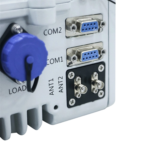
A green input LED and two red output LEDs vary in intensity with changes in the process input and output signals. These provide a quick visual picture of your process loop at all times.
In this article, we''ll take a look at audio splitter circuit diagrams, and how they work. We''ll discuss their various components and what they do, as well as how they might be used in a professional recording
Circuit diagrams for the resistor type splitter are shown below. The output of the 2-splitter has a 6 dB loss, and the output of the 3-splitter has an 8.5 dB loss
Installing the Cable Adapter 1. Connect the RJ45 Connector on the Cable Adapter to an RJ45 port on a Device (Ethernet Patch Panel, Wall Outlet, etc.).
The audio mic splitter circuit diagram is a simple yet effective tool that allows you to build a system of components to split the signal from your
Fig. 3. In a two-way splitter/combiner, equal and opposite currents flow through the internal resistor and transformer, cancel each other, and provide high isolation between ports A and B.
By referring to an easy-to-follow RS232 splitter circuit diagram, it''s possible to construct a reliable setup that''s capable of transmitting data quickly and accurately.
This section delves into the fundamental wiring scheme used for distributing signals across multiple devices from a single source. By grasping the inner workings of this wiring arrangement, one can
Since the 0° power splitter is a reciprocal passive device it may be used as a power combiner simply by applying each signal singularly into each of the splitter output ports. The vector
The LNB splitter circuit diagram typically consists of an input connector for the satellite dish, multiple output connectors for the receivers or set-top boxes, and various passive components such as filters,
How Do Headphone Jacks And Plugs Work Wiring Diagrams My New Microphone Headphone And Microphone Combiners Cable 3 5mm Trrs Audio
A wiring diagram allows you to see the connections between the components in your Ethernet splitter. It is essentially a visual representation of the entire splitter,
This article presents all you need to know about the basic properties, characteristics and applications of a power splitter.
DMX 4X Splitter PC Board The DMX Splitter is a DMX512 1 in 4 out splitter any device that transmits a DMX512 signal and DMX512 outputs, and offers electronic protection using Transient a Voltage
Understanding Power Splitters How they work, what parameters are critical, and how to select the best value for your application. Basically, a 0° splitter is a
Ethernet cable splitter wiring diagrams are available online, usually with detailed instructions as well. Some diagrams are just simple illustrations that
An Ethernet splitter wiring diagram is a great way to set up the different wiring configurations of your device. This diagram will show you how to
Build Your Own MIDI Splitter Hey DIYers, Below is a parts list plus wiring diagrams you will need in order to build yourself your own MIDI Cables and MIDI Splitter.
Audio Splitter Circuit Diagram Audio splitters are useful and sometimes necessary pieces of equipment for many audio professionals. Audio splitters basically allow
A coax splitter diagram illustrates how to split and distribute the signal from a coaxial cable to multiple devices, such as TVs or modems.
Contact us for competitive quotes on any of our power communication and smart grid products
Get a Quote