
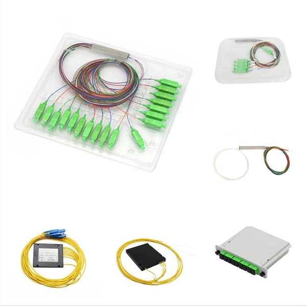
A beam splitter or beamsplitter is an that splits a beam of into a transmitted and a reflected beam. It is a crucial part of many optical experimental and measurement systems, such as, also finding widespread application in.
Grating couplers are simply components of a photonic circuit that use diffraction to couple light into or out of a waveguide. How. A fiber Bragg grating (FBG) is a type of distributed Bragg reflector constructed in a short segment of optical fiber that reflects particular wavelengths of light and transmits all others. This is achieved by creating a periodic variation in the refractive index of the fiber core, which generates a. This SPIE Tutorial Text excerpt discusses the usefulness and versatlity of fiber Bragg gratings. Werneck, Regina Célia da Silva Barros Allil, and Fábio Vieira Batista de Nazaré 10 November 2017 Publications The development of optical fibers has revolutionized not only. A fiber Bragg grating is a periodic or aperiodic perturbation of the effective refractive index in the core of an optical fiber (see Figure 1). 1 Initial Concepts By the 1970s, all telephone cables and microwave links on the planet were saturated.
[PDF Version]
In the UK, consumer units (CU) have evolved from basic main switch and rewireable fuses, that afforded only overload and short circuit protection, into sophisticated control units housing many safety features that can protect against different types of electrical fault.OverviewA distribution board (also known as panelboard, circuit breaker panel, breaker panel, electric panel, fuse box or DB box) is a component of an that divides an electrical power feed into subsidiary. North American distribution boards are generally housed in enclosures, with the positioned in two columns operable from the front. Some panelboards are provided with a door covering th.
This AutoCAD DWG file includes a complete Single Line Diagram (SLD) of a Distribution Board, showing circuit breakers, wiring connections, and load distribution for lighting, power, and mechanical systems. A distribution board or distribution box is where the main power supply is distributed to multiple loads. It is a vital part and central hub of any electrical system. The hub distributes electrical power from a single input source to various circuits throughout a building. You have to connect MCB, RCD, and SP or DP as per your requirements for protection purpose.
This second design is another accurate touch sensitive switch can be built using a single IC 4093 and a few other passive components. The shown circuit is extremely accurate and fail-proof. The circuit is b.
In, an eye pattern, also known as an eye diagram, is an display in which a from a receiver is repetitively sampled and applied to the vertical input (y-axis), while the data rate is used to trigger the horizontal sweep (x-axis). It is so called because, for several types of coding, the pattern looks like a series of eyes between a pair of rails. It is a tool for the evaluation of the combi.
They are single-phase, 3-wire, and can be mounted for top or bottom feed conduit connections. Use with Square D QO circuit breakers. RACO® exposed work covers meet the requirements of the 2014 NEC Article 250. No bonding jumper is required for covers with: (1) Crushed corners (2) Two or more device attachment screws (3) A lockwasher or equivalentConceal live electrical components in circuit breaker boxes to prevent injury and damage. These filler plates snap into panel openings. With a main breaker installed and main service. 4", 6. 5 Cu Inch, Pre-Galvanized Steel, 2-GFCI Receptacle Opening, 1/2" Raised, Exposed, Square Box Surface Cover Square Box Surface Cover; Type Raised, Exposed; Box Size 4 Inch; Opening Type (2) GFCI Receptacle; Raised 1/2 Inch; Capacity 6. Can a standard 20 amp outlet and a 20 amp rated GFCI. Call it Something Else? Loading product details.
[PDF Version]
The objective of relay protection is to quickly isolate a faulty section from both ends so that the rest of the system can function satisfactorily. The functional requirements of the relay:.
Contact us for competitive quotes on any of our power communication and smart grid products
Get a Quote