
This guide provides a comprehensive engineering perspective on ODFs—beyond the basic “what is an ODF” explanation—covering structural design, fiber management, MPO/MTP integration, and selection criteria for modern high-density deployments. Why ODFs are the. An Optical Distribution Frame (ODF) is the central hub for fiber splicing, termination, patching, and cable protection in modern optical networks. It ensures fiber management is structured, minimizes signal loss, and provides accessibility for maintenance and future expansion. Without it, cables get tangled.
An optical Distribution Frame (ODF) or patch panel is the starting point for optical cables, most commonly found in rack cabinets in Head End (HE)/Central Office (CO)/Point of Presence (POP)/Data Centre (DC) or smaller cabinets or enclosures. It is usually a compact and structured framework composed of a steel shell and internal fiber splice tray as the main. In broadband optical fiber access network, we often see the all kinds of fiber box such as fiber cabinet, fiber optic distribution box, fiber optic terminal box, multimedia box, and customer box. What is the difference between these fiber boxes.
An Optical Distribution Frame (ODF) is a dedicated unit designed to organize, terminate, and interconnect fiber optic cables. As data centers, enterprises, telecom operators, and smart-building infrastructures deploy increasingly dense fiber links, ODFs provide the structured. Achieve successful cable management, handle high amounts of fiber cable and add density to fiber frames with the new DCX Optical Distribution Frame (ODF) System which features innovations like flippable cassettes, modular frame design and multiple configuration options. It brings together fiber splicing, patching, and cable routing in a single structure, while shielding sensitive connectors and splices from mechanical stress or. Enter the Optical Distribution Frame (ODF)—a foundational component that serves as the “nerve center” for fiber optic management, enabling seamless connectivity, efficient maintenance, and scalable growth. When fully loaded with EDGE 4U housings the optical distribution frame dual-frame model provides a total capacity of 5,760 LC Duplex or MTP ports / 11,520 LC Simplex ports while the single-frame.
[PDF Version]
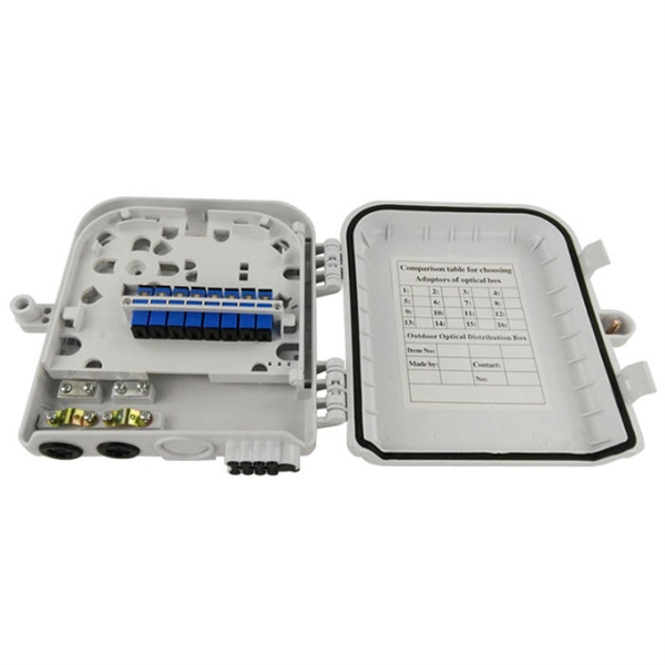
To determine the ideal capacity for a Fiber Optic Terminal Box (FOTB), you must match the fiber count—whether 12-core, 24-core, or 48-core —to your current active subscriber density while allowing for a 20-30% growth margin for future expansion. Fiber core count defines the maximum number of optical terminations or distribution points that a fiber enclosure can support. IP55-rated enclosure supports reliable performance in diverse environments, from urban to rural deployments. Designed for easy wall or pole mounting, accommodating various installation. The 24 Core Fiber Optic Distribution Box With a maximum capacity of 24 cores, it has the capability to splice up to 72 cores in total. Crafted from IP65 ABS+ material, it ensures robust protection and is. TMT GLOBAL provides high-quality odf 24 core wall Mounted Optical distribution Frame multimode OS2 multimode OM2 OM3 OM4 fiber optic equipment for use in various industrial and building automation indoor and outdoor applications.
[PDF Version]
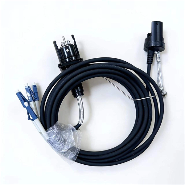
This is where underground splice boxes (also known as underground joint boxes) come into play. These critical components protect fiber optic, power, and communication cables from moisture, mechanical damage, and extreme weather conditions, ensuring longevity and seamless. Underground cables are pulled in conduit that is buried underground, usually 1-1. 2 meters (3-4 feet) deep to reduce the likelihood of accidentally being dug up. In extreme cold climates, cables may need to be buried at greater depths where there temperatures are colder and frost penetrates to. When planning a fiber optic network installation, one of the most common questions is: How deep are fiber optic cables buried? Proper burial depth is critical for the safety, durability, and performance of your communication infrastructure. It acts as a central point for terminating, splicing, and distributing these cables, providing necessary protection and.
[PDF Version]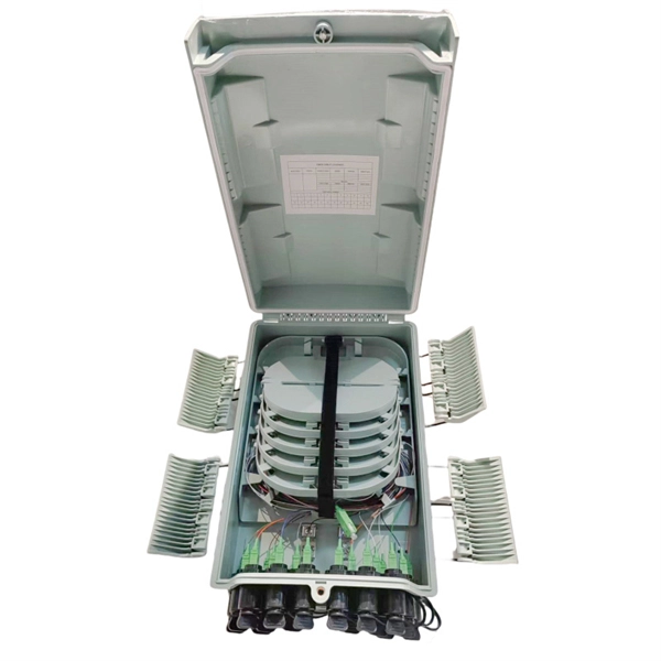
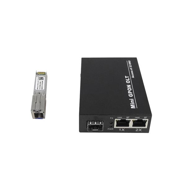
Optical modules used in Remote Radio Units (RRUs) for CPRI applications are required to support industrial temperature ranges, primarily because RRUs operate in diverse outdoor environments with extreme temperature variations. CPRI (Common Public Radio Interface) defines the interface relationship. A remote radio head (RRH), also called a remote radio unit (RRU) in wireless networks, is a remote radio transceiver that connects to an operator radio control panel via electrical or wireless interface. They play a critical role in maintaining signal quality by minimizing loss and interference. Characteristics: Feeders are designed with insulation and shielding to protect against environmental factors. RRU and BBU are crucial components in base station construction, enabling a distributed architecture that improves efficiency and reliability. A key feature of IHS modules is that the heat sink fins are a permanent component of the pluggable module itself. The logical term “distributed and integrated” is because traditionally the radio architecture for cellular system is.
[PDF Version]Contact us for competitive quotes on any of our power communication and smart grid products
Get a Quote