
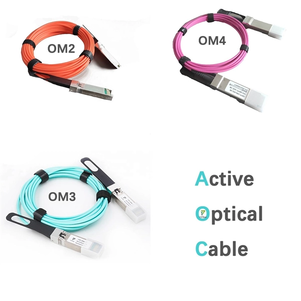
An optical module is a typically hot-pluggable optical transceiver used in high-bandwidth data communications applications. Optical modules typically have an electrical interface on the side that connects to the inside of the system and an optical interface on the side that connects to the outside world through a fiber optic cable. The form factor and electrical interface are often specified by an int. Electrical Interface TypesThere have been multiple variants of the electrical interface of optical modules that have been used over the years. The earliest forms of optical modules had an analog electrical interface. In the transmit dir. Many different forms of optical modulation and multiplexing have been employed in optical modules. The most common modulation technique historically has been or NRZ.
In , a busbar (also bus bar) is a metallic strip or bar, typically housed inside,, and for local high current power distribution, transmission, or switching substations. They are also used to connect high voltage equipment at electrical switchyards, and low-voltage equipment in. They are generally uninsulated, and have sufficient stiffness to be s.
Busbar problems are often incorrectly identified as harmonic currents caused by non-linear loads. According to MET Group's field data, the primary causes of busbar and tap-off switch failures include aging, loosening connections over time, and poorly installed new systems. Fault arcs on busbar sets and switchboards Title Author Subject Fault arcs on busbar sets and switchboards-The probability of appearance of a fault arc on a set of busbars cannot be considered as non-existant. How to reduce arcing probability, limiting consequences. This generates both thermal stress (I²t heating) and mechanical stress (electrodynamic forces between conductors). Bus bar supports spacing, and bracing must be designed to withstand. switchgear busbar sizing decisions should start from voltage class, fault level, and installation environment. Clear interface data reduces site rework between transformer, switchgear, breaker, RMU, and. Additionally, busbar faults can create arc flashes, posing a major safety hazard.
[PDF Version]
When drawing up a single line-diagram, a great number of possible combinations of incoming and outgoing connections have to be considered. The most common ones are shown in the following di.
Front- and rear-access switchboards align at the front and the rear. Bus maintenance and cable entry and exit require rear access. Their placement directly affects current capacity, heat dissipation, copper consumption, cabinet size, and even installation safety. If the main section is deeper than others, due to physical size of the main device, the necessary offset in lineup will occur in front, and the main section will be. A large single panel, frame, or assembly of panels on which are mounted on the face, back, or both, switches, overcurrent and other protective devices, buses, and usually instruments. In most assemblies you will find horizontal main bars, vertical risers, neutral and equipment-ground buses, and purpose-designed. Article 408 covers the specific requirements for switchboards and panelboards that control power and lighting circuits.
In HV and EHV installations and in outdoors MV installations bare busbars and connectors are used and the conductors may be tubular or stranded-wires. The starting point for planning a switchgear installation is its single line diagram. For details about technical design and equipment like e. A conductor or group of conductor used to collect the power from incoming feeders and distribute to the outgoing feeders is known as busbar. In most assemblies you will find horizontal main bars, vertical risers, neutral and equipment-ground buses, and purpose-designed. In 2017, UL 508 harmonized with IEC 60947 for low voltage switchgear and control gear to become UL 60947 - further cementing IEC devices as the industry standard for years to come.
Contact us for competitive quotes on any of our power communication and smart grid products
Get a Quote