
The 45 degree bend for 450mm medium duty cable tray provides a strong and reliable solution for directional changes in cable management systems. Designed for both internal and external applications, this fitting combines durability, corrosion resistance, and easy installation. Armorduct offer a comprehensive range of cable tray including light, medium and heavy duty cable tray and associated accessories to suit various applications. Available in standard and bespoke sizes. Pre-galvanized steel fitting 5 inches side rail height 30 inches width ladder horizontal bend 45 degree 12 inches radius For more info visit: electrification. com Email Address (For your convenience, you can send the page to up to three e-mail addresses at a time. Materials and finishes available are mild. 40150 Shah Alam, Selangor, Malaysia.
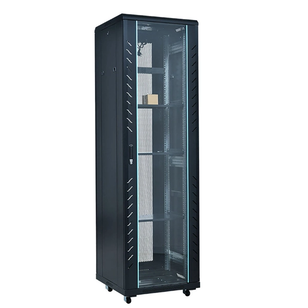
A ladder cable tray is a structural systems design to organize and support cable in commercial or industrial settings. The vertical cable ladders STL, STM and STIC meet the exact specifications and definitions of DIN 4102 Part 12 of November 1998, such as height of the cableladder / tray, width of the cable ladder/ tray, proportion of holes in the cable tray, distance between rungs of the cable ladder, material. Answer: No. NEC section 300-8 does not permit any tube, pipe, or equal for water, air gas, drainage, steam, or any service other than electrical in raceways or cable trays containing. A Vertical Cable Tray is a specialized support system designed to carry electrical and data cables securely in a vertical or riser direction. This tray has two rungs running parallel to each other, and are connected by rungs – looking like a ladder.
The bends, tees, crosses, risers and reducers of wire mesh cable tray can be easily and quickly made live at the project by using a bolt cutter. Since the jaws of the bolt cutter drags a layer of zinc across the cut end and forms a protective layer. Only two splices are required to securely connect tray widths of wire basket tray. Engineers and contractors in North America and around the world have found. How to cut Oglaend System Support Channels, Cable Ladders and Cable Trays.
Mark the support, fix the threaded rod supports with appropriate metal plugs, and then fix the 'L' angles / Slotted 'C' channels with nuts. 2 M distance is maintained between the supports to avoid the sagging of trays and ladders. This publication is intended as a practical guide for the proper and safe* installation of cable ladder systems, cable tray systems, channel support systems and associated supports. Cable ladder systems and cable tray systems shall be manufactured in accordance with BS EN 61537, channel support. en completely installed, without damage either to conductors or structural system use maintain spacing or to keep cables in place when the tray is ect the minimum bend ra-dius for cables as they exit the bottom of the cable tray. During forklift offloading on uneven ground, one must exercise extreme caution to prevent load shifting. Only. cable trays are equivalent.
[PDF Version]
(8 mm) parallel slots (finger ducts) to pull cords through so you can easily organize and route cables in and out of the raceway. In practice, cable tray dimensions are a system of interrelated measurements —width, depth, length, and material thickness—that directly affect cable fill compliance, heat dissipation, structural loading, and long-term expandability. From an engineering standpoint, cable tray dimensions are not. Learn why IT Pros trust StarTech. com for performance connectivity accessories. The mechanical and electrical characteristics, tests, certifications, overall quality management, recommendations mentioned. GSPN755PY1 - Mita - Cable tray slotted 75x50 mm - 3 m - GRP PY1 40150 Shah Alam, Selangor, Malaysia.
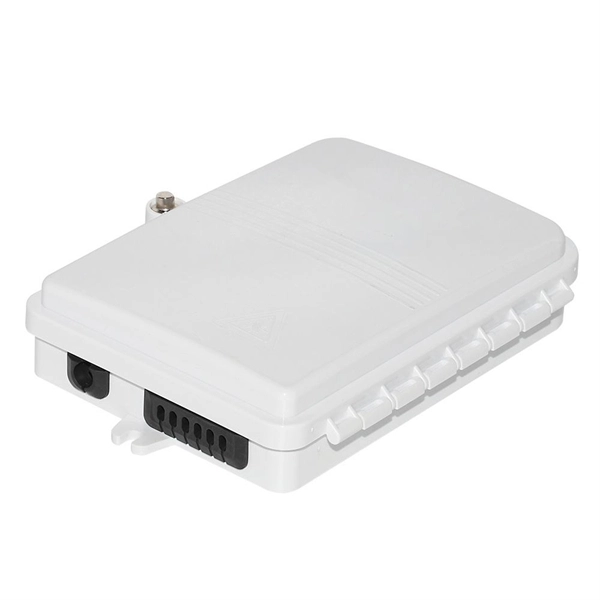
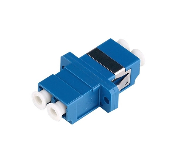
Optical cable tray is a system designed to protect and route fiber optic patch cords, cable assemblies to and from network cabinets, ODF and other terminal devices. Ducting offers ideal solutions for optical raceway requirements and application with pleasing appearance and easy. Cable trays are frequently used for both power and communications cables in industrial applications. Its basic components include: straight grooves, horizontal and vertical elbows, optical fiber outlets, connectors and supports.
Among the most common options are fixed and adjustable cable tray support brackets. The right choice can significantly impact the efficiency and safety of your installation, so it's crucial to understand the differences between these two types. When it comes to organizing electrical cables and conduits, choosing the right support brackets is essential. es in the industrial environment. Our cable support. LB3 brackets can be used for mounting lighting units at adjustable angles and are fixed to both the sidewall and the base of the cable tray. The mechanical and electrical characteristics, tests, certifications, overall quality management, recommendations mentioned in this technical guide only apply to our own cable management ranges and cannot under any circumstances be transposed to si osure, overheating or. en completely installed, without damage either to conductors or structural system use maintain spacing or to keep cables in place when the tray is ect the minimum bend ra-dius for cables as they exit the bottom of the cable tray.
[PDF Version]Contact us for competitive quotes on any of our power communication and smart grid products
Get a Quote