
Scientists at the University of Southampton have developed a radical new hollow-core optical fiber that carries light through air instead of solid glass. The result? Data that moves faster, farther, and with a thousand times more transmission power than today's networks can handle. Hollow-core optical fibers (HCFs) have unique properties like low latency, negligible optical nonlinearity, wide low-loss spectrum, up to 2100 nm, the ability to carry high power, and potentially lower loss then solid-core single-mode fibers (SMFs). However, glass imposes a fundamental physical limitation because light travels through it approximately 30 percent slower than through air. Recent advances in reducing optical losses and the prospects for telecommunication applications of hollow-core fibers, issues of transporting high-intensity optical radiation, and results on nonlinear compression and the generation of ultrashort pulses in gas-filled hollow-core fibers are reviewed. This isn't just. In addition to beating conventional telecom fiber on loss and latency, hollow-core fibers are enabling new approaches to applications like sensing, fiber lasers and optical tweezers.
[PDF Version]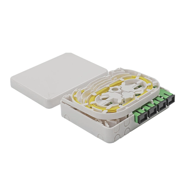
This paper explains why it is not necessary to do so, based on the attenuation properties of optical fibers and the testing that is done by the fiber manufacturer. |OM2, OM3 and OM4 multimode fibers have traditionally been measured for attenuation at 850 and 1300 nm. The core diameter, cladding diameter and concentricity are the most important factors on how well one can connect or splice two fibers. However, LEDs are not coherent sources.
A novel five-tube nested double C-type single-polarization hollow-core anti-resonant fiber (HC-ARF) is proposed for single-polarization single-mode, ultra-low loss, and broadband characteristics. Differen.
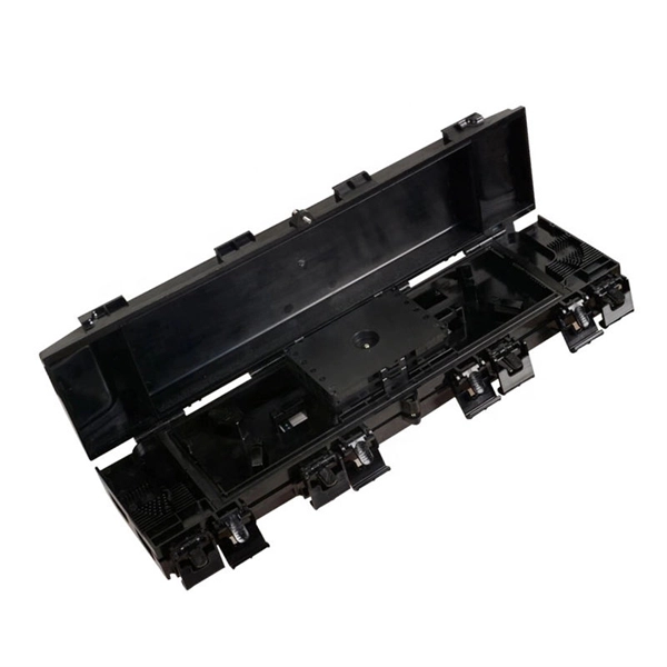
A fiber-optic cable, also known as an optical-fiber cable, is an assembly similar to an but containing one or more that are used to carry light. The optical fiber elements are typically individually coated with plastic layers and contained in a protective tube suitable for the environment where the cable is used. Different types of cable are used for in different applications, for exa.
The number of individual fibers in the cable is usually marked with the fiber count in a clear and consistent format, such as “ 12F ” for a cable containing 12 fibers or “ 24F ” for a 24-fiber cable. The ANSI/TIA-598-C standard defines the color coding system and labeling requirements for fiber optic cables used in premises cabling. These markings and color codes help ensure the accurate identification of individual fibers within cables, making installation, troubleshooting, and maintenance. The text on the cable starts with the Corning product name "Corning Rocket Ribbon (TM) Optical Cable," date of manufacture "01/2022" and a serial number., 48, 96, or 144 fibers), the industry uses a “Tube and Fiber” system. The 12-color sequence is applied twice: first to the outer Buffer Tube, and then to the individual Fiber inside it. Fiber cables have multiple layers where color coding is.
[PDF Version]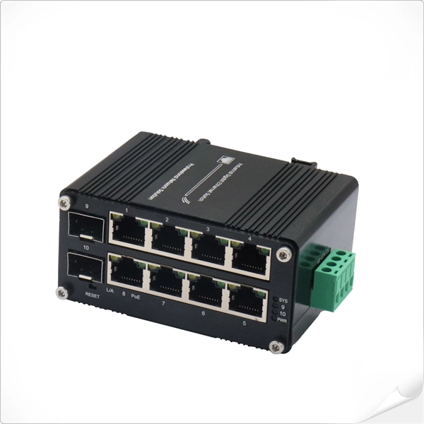
Optical fibers typically work on the principle of total internal reflection of light. It consists of thin strands of glass or plastic fibers through which light pulses are used for transmitting digital and analog data signals, including telephone, internet, and television signals. At present, these cables are used for communication like sending images, voice messages, etc. Light acts as a carrier wave and can be modulated to carry information. Optical fibre is preferred over electrical cabling for long-distance transmission. Imagine what they'd make of modern fiber-optic cables—"pipes" that can carry telephone calls and emails right around the world in a seventh of a second! Photo: Light pipe: fiber optics means sending light beams down thin strands of plastic or glass by making them bounce repeatedly off the walls.
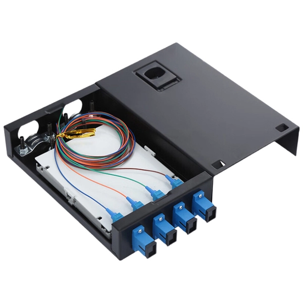
In this lesson, we will identify and examine cables, then prepare them for splicing or termintion by stripping the cable to expose the coated fibers. It provides an expert-curated supplier directory, buyer-focused technical background information, and structured selection criteria to support professional procurement decisions. What are Fiber Strippers? Optical fibers are. In this video, we demonstrate the complete step-by-step process of fiber optic fusion splicing using the Fujikura 66S+ fusion splicer. What is Fiber Optic Splicing and Why is it Needed? – #1. Use and Maintain Your. Marcel Buijs, EMEA Business Development, Technical Sales, Fiber Optic Center, Inc. And tools used for fiber fusion: fusion splicer; fiber cleaver; cable stripper; fiber optic stripper; alcohol;.
Single-core fiber optic cables consist of a single strand of glass fiber. As it only has one core, installation and management are straightforward. This post will guide you through understanding fiber optic cores and selecting the perfect cable for. The number of optical cores in an optical fiber is the total number of equipment interfaces multiplied by 2, plus 10% to 20% of the spare quantity, and if the communication mode of the equipment has serial communication and equipment multiplexing, you can reduce the number of cores. The number of. Common fiber cores include 1 core, 2 cores, 6 cores, 8 cores, etc. When selecting fiber, the first step is to determine single mode or multimode, and. The number of fiber pairs within a fiber optic cable can vary greatly depending on the cable's intended use, the technology employed, and the specific requirements of the network it supports.
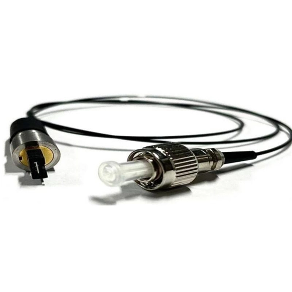
This paper describes a newly developed butt joint type hollow-core fiber connector with protected fiber ends. It can typically realize nearly 0.5-dB insertion and 45-dB return loss without physical contact. I.
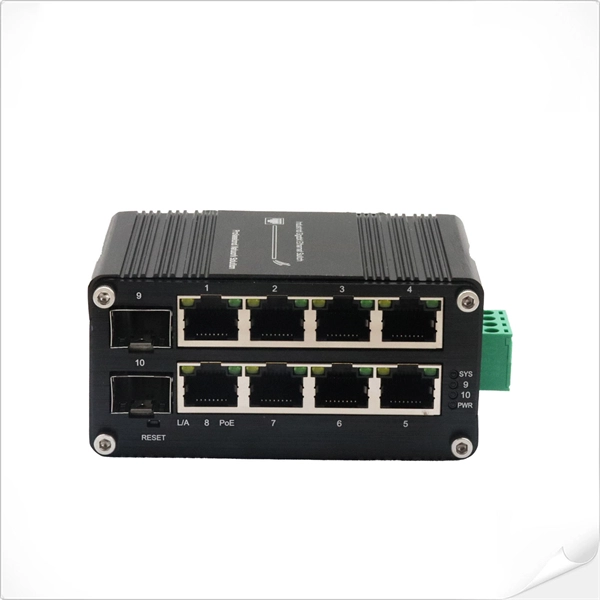
Optical transceiver interoperability refers to the ability of transceiver modules from different manufacturers to function correctly with a range of networking equipment—switches, routers, servers, and optical transport gear—without compatibility issues. This guide dives deep into the core aspects of optical transceiver compatibility, common. When it comes to the connection between two fiber optic transceivers, the following four factors should be taken into considerations: wavelength, speed, fiber type, and the connection to switches. In a fiber link, the data is transmitted from one end to another, and fiber transceivers are. Several years ago, hyperscale network operators saw an opportunity for coherent Dense Wavelength Division Multiplexing (DWDM) transport optics to plug directly into routers for 400 Gbps Data Center Interconnections (DCIs) with reaches up to 120km. This point-to-point, IP-over-DWDM architecture. MSA (Multi-Source Agreement) standards define the mechanical, electrical, and management interfaces of optical transceivers, enabling multi-vendor interoperability, supply chain flexibility, and large-scale network deployment.
[PDF Version]Contact us for competitive quotes on any of our power communication and smart grid products
Get a Quote