
The TFT (Thin-Film Transistor) screens used in relay protection applications play a pivotal role in providing operators with clear, actionable information in real-time. Its modular design and powerful DIGSI 5 engineering tool provide tailored solutions. This reference design showcases a two-dimensional (2-D) Qt graphical user interface (GUI), which is typical for. presentation of protection and control relaying. The report will identify methodology behind these practices, present issues raised by the integration of microprocessor relays and the internal logic and external communication configurations, ying. The first numerical relays were released in 1985.
The article provides an overview of protective relaying principles and their applications for high-voltage power system components. It covers the protection methods for generators, transformers, buses, and transmission lines using various relay types to detect and isolate faults efficiently.
The metal box of the distribution box, the electrical installation board, and the metal base and casing of the electrical appliances in the box must be grounded. The protective neutral wire should be reliably connected through the terminal board. Are you expecting any of those 6 switches will require a neutral connection? @RobertChapin Does not. But it does require panelboard with a neutral that has more than 10 percent of its overcurrent devices rated 30 amperes or less to be protected against overcurrent by a device that has a rating not greater than that of the panelboard. It includes isolator, RCCB (Residual current circuit breaker) or RCD (Residual-current device) devices, protective fuses or MCB's (Miniature Circuit Breaker).

Remove the CPU module from the relay housing and set aside. Be certain to align the printed circuit board with the card guides in the housing. Always use antistatic bags for transporting modules Remove AC power and DC power from the PCD before removing, installing or wiring any of the PCD modules. Consult. What are the steps for safely removing and reinstalling a PLC CPU module? Safe removal and reinstallation of a PLC CPU module requires strict adherence to proper procedures to prevent equipment damage, data loss, or safety hazards. Consult the most recent PCD Instruction Book for details on programming the new CPU to suit your requirements. 0 or Modbus ASCII communications, protocol documentation is available. 1. 1 INTRODUCTION TO THE UR The GE Universal Relay (UR) series is a new generation of digital, modular, and multifunction equipment that is easily incorporated into automation systems, at both the station and enterprise levels. In particu-lar, one will find: General information with regard to design, configuration, and operation of SIPROTEC 4 devices are set out in the SIPROTEC 4 System Description /1/.
[PDF Version]
For testing high-voltage microcomputer protection devices, it is recommended to use a microcomputer relay protection tester capable of simultaneously outputting three-phase voltage and three-phase current, and equipped with timing function for digital inputs. Meet all test requirements on site. It can simulate various operating conditions of the power system, such as normal.
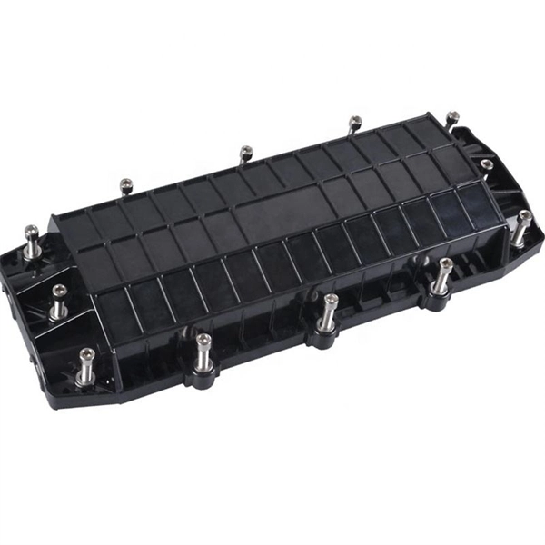
Polyethylene (PE) is the material of choice for use as an aerial OSP cable jacket. The performance of raw PE can degrade rapidly through exposure to sunlight but the addition of carbon black to the cable jacket absorbs the UV light to protect the plastic jacket of the cable. Fiber optic cables enable high-speed, long-distance data transfer, forming the backbone of modern communication. Yet, outdoors, they face temperature swings, moisture, UV exposure, rodents, and human interference. This guide covers how to. Deploying fiber above ground on poles or towers removes the need for underground digging and is particularly useful when the ground is uneven, rocky or both. Some are self-supporting, requiring no separate messenger wire between poles to support the cable's weight. As the leading world manufacturer of fiber optic cable, AFL is uniquely positioned to provide a full line of. Aerial work mixes mechanical engineering (span, sag, tension), careful selection of cable types (ADSS, figure-8, lashed) and a disciplined safety-first attitude.
[PDF Version]
Phase comparison Technique (PCT) is a type of protection by which the quantities are conveyed through communication channels rather than wired interconnections of the relay input devices and it detects both phase and ground faults simultaneously. The phase comparison relaying principle is a line of differential relaying that compares the phase angles of the current entering one terminal of a transmission line with the phase angles of the current entering all the remote terminals of the same line. During normal conditions or through faults the currents. Why are seal-in and 52a contacts used in the dc control scheme? In a typical feeder OC protection scheme, what does the residual relay measure? Questions? 00000001 00000101 00001001 00100100 10010000 :. 51P1P Pickup 51P1C Pickup Type 51P1TD Time Dial 51P1RS Electromechanical Reset? (Y / N) 51P1CT. protective system, Components of Protection System. Sequence Components and Fault Analysis: sequence impedance, fault calculations, Single line to ground fault, Line to ground fault with Zf, Faults in Power syst ional relays, Distance relays, Differential relays. Those categories are directional comparison and phase comparison.
[PDF Version]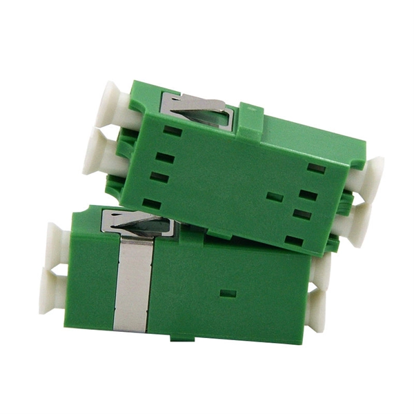
The IEC 61439-1 sets the thermal limit in busbars working at the maximum working load. Here, 140°C (which is 105K over the ambient temperature of 35°C) is the upper safe temperature limit. Continuous, real-time busbar temperature monitoring and hot spot detection for MV & HV switchgear, substations and power plants — EMI-immune, calibration-free, fully SCADA-integrated. Thermal monitoring locations include: Eaton Exertherm CTM solution for MV switchgear. Standards mandate that busbars, when carrying their rated continuous current for extended periods, must not experience excessive temperature rise.
Contact us for competitive quotes on any of our power communication and smart grid products
Get a Quote