
Troubleshoot the problem by following these steps: Confirm that both ports are not shut down. Check that the optical module model, wavelength, speed, and distance match. If the optical module is installed on a GE port, run the display interface GigabitEthernet x/x/x command to check information about the port, including the rate and wavelength. The SFP/Media Converter is designed for easy use in optical fiber transmission. There are no specific requirements for this document. This includes Doppler. First, the transmission class of the optical module fault investigation and solution method This type of optical module failure mainly includes port not UP, port status is UP but do not receive or send messages, port frequently up or down and CRC error.
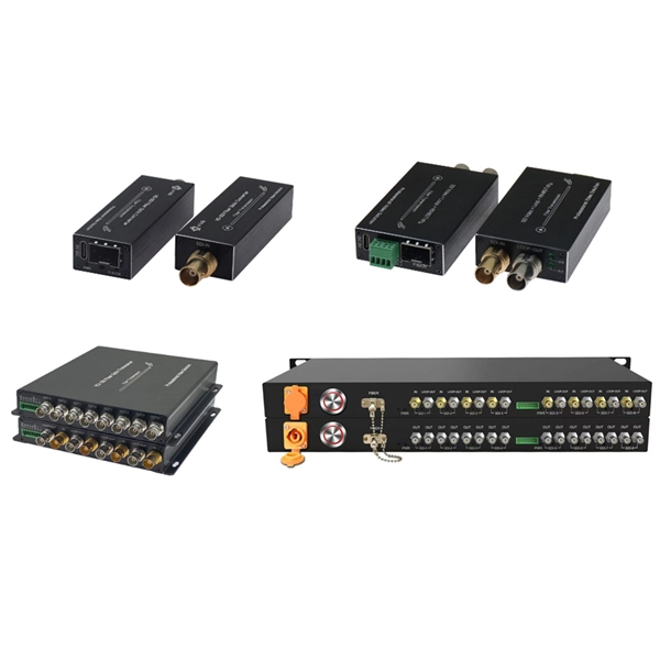
The O2E is a high bandwidth, broadband optical to electrical converter available in a range of configurations. “Auto-Negotiating” is s pported on the copper interface side. According to different rates, encapsulation types and interface types, optical modules can be divided into different categories, one of which is the electrical port module. In the daily enterprise networking, compared with the. 45 Optical to Electrical Converters from 7 manufacturers listed on GoPhotonics Optical to Electrical Converter, also known as an optoelectronic converter, is an electronic device that converts optical signals into electrical signals.
Optical Flow uses a downward facing camera and a downward facing distance sensor for velocity estimation. It can be used to determine speed when navigating without GNSS — in buildings, undergr.
If the optical module is faulty, replace it with the spare part. If. Taking 10G SFP+/XFP optical module as an example, when the optical port of the optical module can not be UP when interconnecting with other devices, it can be troubleshooted from the following five aspects: The first step is to check whether the rate and duplex mode of the ports at both ends match. The following command shows how to enable the transmitting optical power alarm on port e8/1, set the maximum and minimum values, and clear the alarm thresholds. When troubleshooting potential causes: Determine if the downstream. 1) Unused protection: When an optical module is not in use, a dust cap must be installed to prevent dust from entering the port and causing poor contact. 2) Cleaning specification: Use special wiping paper or dust-free cotton swab to wipe the end face in the same direction.
Researchers in the past have analyzed the detrimental effects of the dispersion in optical channels. However, efficient techniques of management of dispersion effects are limited, as huge data is aggregated, w.
Contact us for competitive quotes on any of our power communication and smart grid products
Get a Quote