
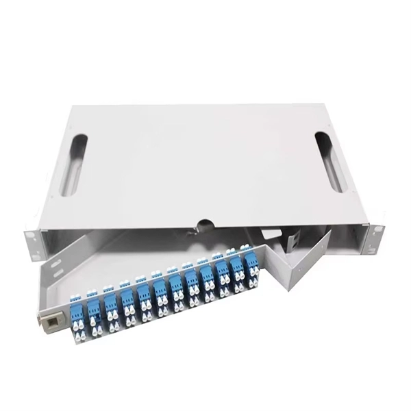
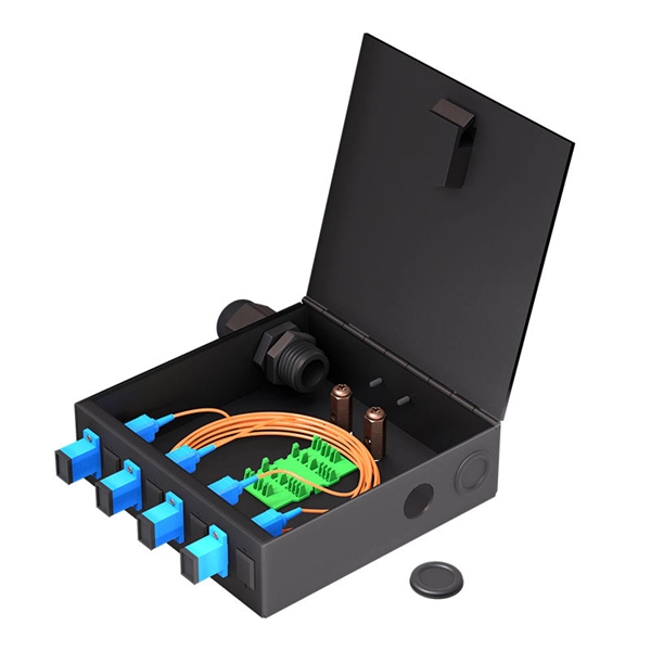
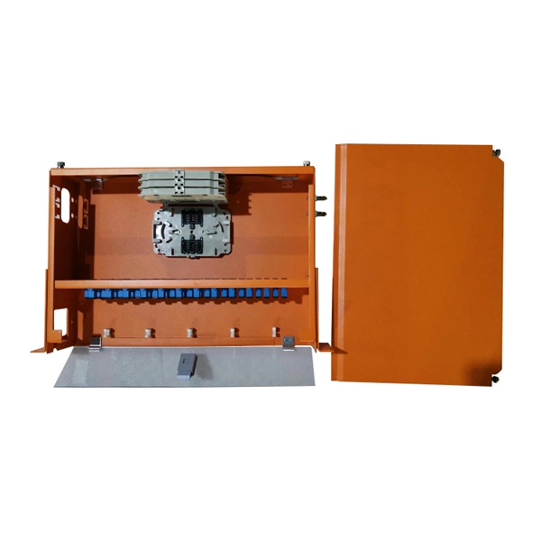
The fundamental calculation formula is: Total patch cords = Total number of device ports × Connection factor Where the connection factor depends on the connection method: 2. Scenario-Based Calculations The redundancy factor is typically 0 (no redundancy) or 1 (1:1 redundancy). the list of patch cords that fulfill the requirements and can be made to order. It covers LC connectors, LC patch cables, uniboot designs, armored. Premium-Line 19” Rack mountable fiber optic patch panel is designed for both patching and splicing, accepts whole range of adapters including SC, ST, FC, LC adapters. 2 * Rear cable entries accommodate cables with diameter below 10mm. More detailed calculation is available in our software. Accurate length fixing is a crucial aspect in planning, with the goal of ensuring efficient, safe, and future-proof implementation of fibre optic patch cords. They are manufactured and tested in compliance with TIA 604 (FOCIS), IEC 61754 and YD/T industry standards.
[PDF Version]
This calculator provides various calculations related to fiber optics, including V-number, numerical aperture, critical angle, and propagation constant. Calculation Example: The calculations provided in this calculator are essential for understanding the behavior of light in optical fibers. It has an intuitive graphical user interface with tabs for the following purposes: Your browser does not support the video tag. Functions: modulus, modulus Modulus of a number is the remainder when that number is divided by another number. Single mode fibers support one mode. In order to accurately study optical modes, the complete Maxwell equations are to be solved. There are no specific requirements for this document.
The Cable Tray Slope & Fabrication Calculator is a field-ready tool for electrical construction workers who need to quickly calculate V-cut dimensions, bolt hole positions, slope length, and hanger spacing for inclined cable tray installations. Select the bend direction (vertical or horizontal). The right cable tray sizing calculator helps engineers turn cable schedules into a verified tray width and fill check before material ordering and site installation. Follow these simple steps: Define Tray Dimensions: Enter the width and depth of your planned cable tray (in mm or inches). A properly designed and installed cable tray system will provide. Cable tray fill is the proportion of usable cross-sectional area inside a cable tray occupied by installed cables.
This guide provides a comprehensive overview of various transformer protection schemes and offers recommendations for relay selection, coordination, and settings. Another important standard is the IEC 61850, which focuses on communication protocols for substation automation systems. Table 1 – Transformer fault types/protection methods 1. In HV (High Voltage) and MV (Medium Voltage) substations, relay protection safeguards critical assets such as transformers, circuit breakers, and lines. • If current penetrates the limits of the thermal damage curve, insulation damage may occur.
This guide focuses primarily on application of protective relays for the protection of power transformers, with an emphasis on the most prevalent protection schemes and transformers. Principles are empha.
Tower Height: The exact vertical height required. . A telecommunication tower quotation represents a comprehensive pricing document that outlines the costs, specifications, and implementation details for cellular communication infrastructure projects. This essential document serves as the foundation for network expansion initiatives, providing. Telecom tower pricing typically ranges from $15,000 to over $150,000 for the structure itself, heavily dependent on height, design type, and current global steel prices. A standard 40-meter lattice tower might cost significantly less than a camouflaged monopole of the same height due to design. This comprehensive article examines the critical aspects of structural evaluation in telecommunications towers, addressing key considerations in design, load analysis, and safety protocols. The article encompasses various tower configurations, including lattice, monopole, and guyed structures.
[PDF Version]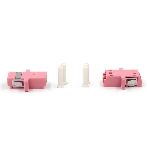
Calculate the necessary length of material to form elbows, considering the inner radius and degree of the bend to minimize material stress. The method for producing bridge bend elbows is as follows: Take a 90-degree cable tray bend elbow as an example, and apply the same principles for 45-degree bends accordingly. The length of the bottom side (bottom diagonal) after bending the cable tray should be equal to the width of the cable. This manual is designed to guide workers through the detailed production process of ladder cable trays, including the manufacture of horizontal elbows, tees, crosses, reducing bends, and vertical bends, with emphasis on precision, safety, and quality control. A rung spacing of 6 to 9 inches (150 to 230 mm) is preferable when the cable tray cont d for instrumentation and control applications that require additional protec eferred to support and protect numerous small. Unitray Systems Inc. is an Edmonton based company dedicated to excellence in the manufacturing of electrical ladder tray.
[PDF Version]
The calculator employs NEC Article 314. 16 formulas to determine required box volume. The basic formula is: Required Volume = (Number of Conductors × Volume per Conductor) + (Number of Devices × 2 × Volume per Conductor) + (Number of Fittings × Volume per Conductor). The information provided in this document contains general descriptions, technical characteristics and/or recommendations related to products/solutions. This document is not intended as a substitute for a detailed study or operational and site-specific development or schematic plan. It is not to be. Electro Centers or Integrated Power Assemblies (IPA) can be fitted out with a variety of electrical distribution equipment and shipped to the site in preassembled modules for mounting on elevated foundation piles, building setbacks or rooftops. Before we dive into calculations, let's get familiar with a few essentials: 1. Power Supply is 430V (P-P), 230 (P-N), 50Hz. The calculation is based on the following standard volumes: The formula is: [ text {Box Size} = (text {Number of Wires} times 2.
[PDF Version]
Sag calculation follows the parabolic approximation for level spans: Sag = (w × L²) / (8 × H), where w = cable weight per unit length (e. 12 kg/m for a 12-fiber ADSS), L = span length (meters), and H = horizontal tension (kN). Also known as ultimate tensile strength or breaking strength, it refers to the calculated value of the sum of the strength of the load-bearing section (mainly counted as spinning fiber). Entering a few cable characteristics and climate conditions, you'll get the. Installing ADSS cables on existing power towers requires calculating sag and tension at the maximum operating temperature of 85°C. 8 meters; at 85°C, sag increases to 4. Loading - The amount of. Fittings used with ADSS cable may be tension type, used at dead-ends where the cable terminates or changes direction, or may be suspension type, only holding the weight of a span with tension transmitted through the next span of cable. Reinforcing rods are used at dead-ends and may sometimes be.
[PDF Version]Contact us for competitive quotes on any of our power communication and smart grid products
Get a Quote