
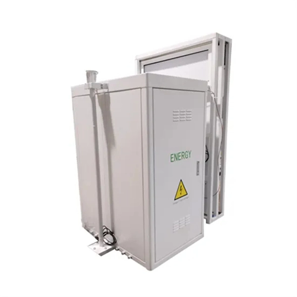
13-circuit waterproof distribution box, single-row design with bottom opening for easy wiring and maintenance. IP65 sealing and PC/ABS housing for reliable indoor/outdoor performance and impact resistance. The building's electrical power enters through the main feeding cable, which connects to the distribution board. But what exactly is a power distribution box, and why is it so essential in our daily lives? The DB panel board controls the flow of electricity. A distribution board (also known as panelboard, circuit breaker panel, breaker panel, circuit breaker, electric panel, fuse box or DB box) is a component of an electricity supply system that divides an electrical power feed into subsidiary circuits while providing a protective fuse or circuit. An electrical panel box, also known as a breaker box or a distribution board, is a crucial component of any electrical system. Main Distribution Board (MDB) 2.
[PDF Version]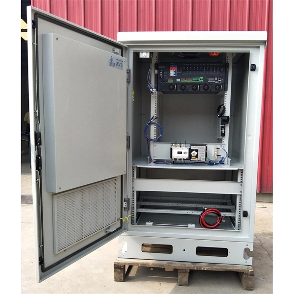
Check your surge protector for burn marks or melted parts. These signs mean it might fail and harm your devices. If you notice too much heat or if a circuit. Be sure to have surge protectors where necessary, as this is very important for protecting electronics from rises in voltage. Cracks, melted parts, color changes and unusual heat or burning smells are physical indicators to watch out for. Regular testing and proper SPD maintenance — including MOV/GDT.
The shield should be connected at each end of the cable to the machine earth via an electrically conducting connection with a large surface area and low impedance. the twisting together and point contact of the shield, should be avoided. Their seemingly simple nature belies the critical role they play in ensuring the proper functioning and safety of a wide range of applications, from automotive wiring to industrial machinery. We'll show you why professionals consider this technique. The electrical panel, often called the load center, distributes power throughout a home's electrical system. Modern residential systems rely on advanced safety devices like Arc-Fault Circuit Interrupters (AFCI) and Ground-Fault Circuit Interrupters (GFCI) to meet code requirements. The schematic, located on the wiring diagram, will i dicate the positions where these breakers can cator flags disappear when the load wires are LED i cators for troubleshoot Types QTA, QTAN Thermal. In this model, a fault is represented as a mutable, stateful, and persistent MO. Package features on back label use different wordage, but actually say the same.
[PDF Version]
This guide discusses common cable tray problems, from loosening and corrosion to grounding issues and installation errors, along with strategies for prevention and resolution. Understanding the root causes of cable tray failures is the first step toward ensuring system reliability. Atomic Taco from Seattle, WA, USA, CC BY-SA 2. As most of cable failure root causes can be traced back to manufacturing, installation and operation phases, ideally cable asset management should begin at an. Cable accessories are often the most prone to failure of any part of the cable system.
Abstract: This study presents a coupled electric–magnetic–thermal–mechanical analysis of various busbar arrangements under short-circuit conditions. The open construction of busbars increases the risk of faults, e. by the ingress of foreign bodies into air gaps, and the risk of consequent damage is high due to their high normal operating. Multiphysics analysis of busbars with various arrangements under short‐circuit condition IET Electrical Systems in Transportation Research Article Multiphysics analysis of busbars with various arrangements under short-circuit condition ISSN 2042-9738 Received on 23rd April 2016 Revised 19th June. Busbars in power systems are the location where transmission lines, generation sources, and distribution loads converge. Common copper busbar faults primarily stem from electrical and mechanical stresses, often leading to reduced performance or system failure.
[PDF Version]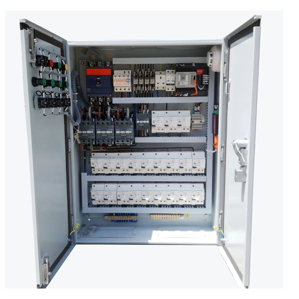
Brazil has an administrative system for internet conflicts – SACI-Adm – created in 2010, it has solved conflicts related to domains under the “. with the support of the Brazilian Internet Management Committee (CGI. br), SACI-Adm was implemented by the Information and. In the dynamic digital landscape of Brazil, disputes over domain names can often arise when multiple parties lay claim to the same. Such conflicts can be rooted in various factors, including trademark infringement, cybersquatting, and domain name similarity. To ensure fair and. Further to the update of the. br Policy (Regulamento do Sistema Administrativo de Conflitos de Internet Relativos a Nomes de Domínios sob o ". br"– denominado SACI-Adm), published by the NIC. br go when it comes to solving these matters. BR, any entity legally established in Brazil (whether legal entity or private person) can register.
[PDF Version]
Busbar problems are often incorrectly identified as harmonic currents caused by non-linear loads. According to MET Group's field data, the primary causes of busbar and tap-off switch failures include aging, loosening connections over time, and poorly installed new systems. Fault arcs on busbar sets and switchboards Title Author Subject Fault arcs on busbar sets and switchboards-The probability of appearance of a fault arc on a set of busbars cannot be considered as non-existant. How to reduce arcing probability, limiting consequences. This generates both thermal stress (I²t heating) and mechanical stress (electrodynamic forces between conductors). Bus bar supports spacing, and bracing must be designed to withstand. switchgear busbar sizing decisions should start from voltage class, fault level, and installation environment. Clear interface data reduces site rework between transformer, switchgear, breaker, RMU, and. Additionally, busbar faults can create arc flashes, posing a major safety hazard.
[PDF Version]Contact us for competitive quotes on any of our power communication and smart grid products
Get a Quote