
What Is a Distribution Box?A distribution box, also known as a power distribution unit, is a critical component in any electrical system. It is the control center fo.
Many (MSAs) have come and gone over the years in the optical module industry. The (SFP) MSA has specified many optical module form factors over the years. • Small Form-factor Pluggable (SFP).
With CPO, inspecting or replacing faulty optics takes much longer. Worse, a failed optical port embedded in the package means reduced switch throughput, with no easy replacement. These concerns aren't new, but the industry has made significant strides in the last two. Co-packaged optics (CPO) technology, a key enabler for next-generation data center architectures, promises unprecedented bandwidth density and power efficiency by tightly integrating optical engines with switch silicon. But after nearly a decade of existence, where does this next-generation optical. These pressures are driving renewed momentum behind co-packaged optics (CPO). 9B by 2029, fueled largely by AI data centers. This proximity reduces power consumption dramatically. As power consumption continues to surge with the rapid expansion of AI data centers, expectations are high that CPO will dramatically. OFC 2025 made one thing clear: The transition to Co-Packaged Optics (CPO) switches in data centres is inevitable, driven primarily by the power savings they offer.
[PDF Version]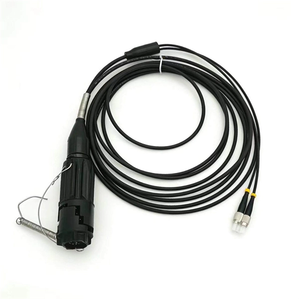
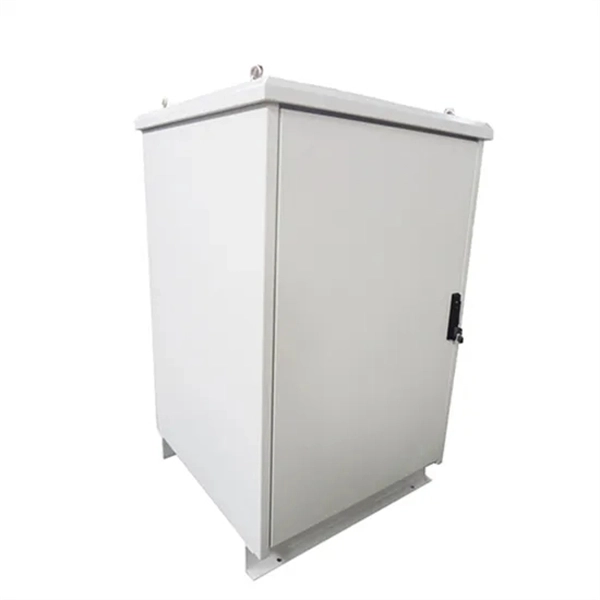
This transparent protective cover is designed for panels and control cabinets, providing maximum protection in demanding industrial and environmental conditions. (2) Flexible options including plastic waterproof distribution box and DIN rail waterproof electrical distribution box for versatile wiring needs. - The folding structure and automatic buffer closure make it easy to open and close the power supply cover of this switch box. Outdoor Waterproof Enclosure Box originally developed for modern industrial and residential applications, the TSM series. These covers are designed for a limited number of circuit breakers in residential or small commercial settings where electrical loads are lower and where only one phase of electricity is needed.
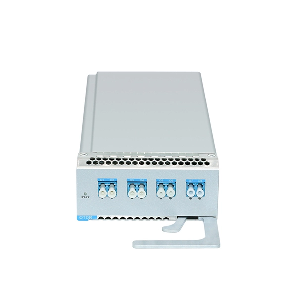
Strain relief bar (SRB) is a cable management solution, which in most cases, attaches to the back of the rails via the strain relief bar brackets. It also helps you arrange interface cables in such a way that the power modules, fan assembly, and air filte n for the Cisco 10005 router. The cable management bracket enables you to route the cables outside the router and away from the Routing Engines and LMICs. Figure. These rack types are broken down in Table 2 into 4-post and 2-post styles. 4-post rack types contain vertical mounting flanges with either square-hole, unthreaded round-hole, or threaded round-hole designs as part of the rack and rail interface. This washer is not installed. The following guidelines provide cabling information for installing, migrating, relocating, or upgrading your system: Position drawers in racks to allow enough space, where possible, for cable routing on the bottom and top of the rack, and between drawers. Shorter drawers must not be placed between.
[PDF Version]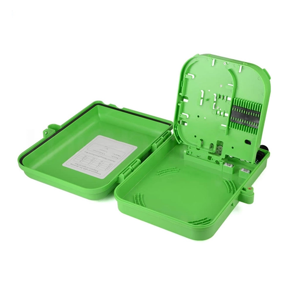
Fiber optic splicing is the process of joining two optical fibers end-to-end. Unlike using connectors, which are designed for frequent connection and disconnection at patch panels, splicing creates a permanent, stable joint with minimal light loss. The optical fiber elements are typically individually coated with plastic layers and contained in a protective tube. Fiber optic cables are the invisible highways of our digital world, carrying massive amounts of data at the speed of light. Fusion Splicing: This method involves aligning the ends of the two fiber optic cables and then fusing them together using heat. This creates a permanent and low-loss connection. Thin strands of glass bundled in cables and stretched across continents and oceans make possible much of what we take for granted today, such as the Internet, Zoom calls, electronic. The existing 2" conduit contains 4x 1/0 XLPE cable (rated for direct-burial), so I plan on pulling outdoor rated, non-metallic fiber through the same conduit. My original plan was to trench new conduit and run CAT8, but given that the existing run is all "customer side" and installed by the former.
[PDF Version]Contact us for competitive quotes on any of our power communication and smart grid products
Get a Quote