
Strain relief bar (SRB) is a cable management solution, which in most cases, attaches to the back of the rails via the strain relief bar brackets. It also helps you arrange interface cables in such a way that the power modules, fan assembly, and air filte n for the Cisco 10005 router. The cable management bracket enables you to route the cables outside the router and away from the Routing Engines and LMICs. Figure. These rack types are broken down in Table 2 into 4-post and 2-post styles. 4-post rack types contain vertical mounting flanges with either square-hole, unthreaded round-hole, or threaded round-hole designs as part of the rack and rail interface. This washer is not installed. The following guidelines provide cabling information for installing, migrating, relocating, or upgrading your system: Position drawers in racks to allow enough space, where possible, for cable routing on the bottom and top of the rack, and between drawers. Shorter drawers must not be placed between.
[PDF Version]
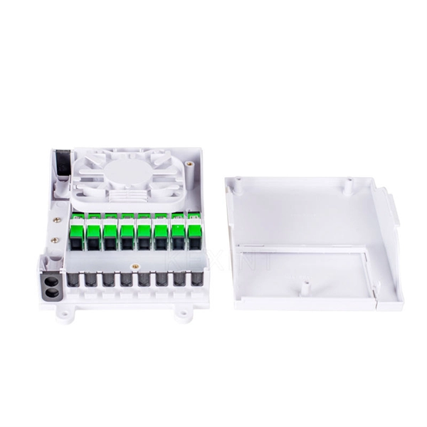
Begin by routing each fibre patch cable through the designated cable pathways. Use structured systems like cable trays, ducting, or raceways to prevent clutter and protect fibres from damage. Correct patch-cord installation is essential for maintaining low insertion loss, stable return loss, and long-term reliability in both indoor and outdoor fiber networks. Proper handling, routing, cleaning, bend-radius management, and connector alignment ensure that the optical link meets design. Incorrect routing, contamination, or physical stress on a fiber optic cable can result in attenuation, signal loss, and even complete link failure. According to data from NS Comm's Fiber Performance Lab (2024 Q4 Test Report), poor installation practices can cause up to 2. 5 dB additional signal loss. Proper cable routing, clean connector mating, and adherence to bend radius guidelines aren't optional—they're essential for sustaining long-term network performance and infrastructure lifespan. Ground Outlet: Cables enter inside the rack from the bottom, meaning the patch panel should be mounted in the lower part inside the rack.
[PDF Version]
The hot wire (usually black) carries live current from your breaker panel. Green or bare copper ground wires provide emergency pathways for stray voltage. Cable trays: Cable rails are flat structures that can hold several cables at the same time. EMC stands for Electromagnetic Compatibility. However, the idea is always the same - electrical devices are not allowed to interfere with each other. The purpose of this presentation is to introduce some practical methods. Signal cables or weak-current cables inside cabinets are sorted by cable managers, cable rings, and cable trays. Power enters through connectors like WAGO 221 lever nuts, splitting into two directions. "Proper conductor. Certain preconditions in the Engineering Base project must be fulfilled to get an errorless routing when using the assistant Cabinet Routing. After the successful execution of the Cabinet Routing the worksheet “Routing Infor-mation” is displayed which contains information about the routed wires.
[PDF Version]
Modelling tools enable fast and efficient design of cable tray and conduit systems Pre-definition of routing preferences enables fast and efficient design. Select a containment product and define alignment, elevation, offset, and bend and branch types and you are ready to start. What is the QR Code Tray Labels feature? With Pro, you can generate a unique QR code for each cable tray. Print and attach the label during manufacturing or installation. ESAPRO Cable Trays Software is your ally in 3D cable tray design. Cable design software by. The electrical design application is an optional add-on for the M4 PLANT plant design and factory layout software. The application provides powerful routing tools for loading, positioning and replacing 3D electrical routing components and control systems, either manually or automatically. Paneldes Raceway is the 3D CAD design module of EDS used for the creation of Plant Raceway models. In addition to standard programs.
[PDF Version]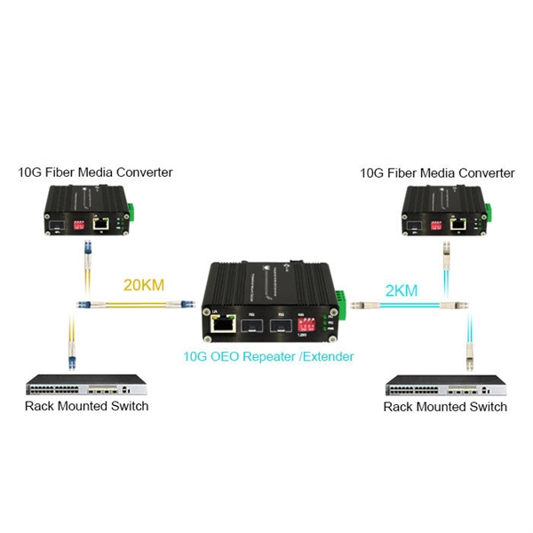
Ladder-type trays are ideal for heavy-duty power cables, offering excellent ventilation and structural support over long spans. As one of the established cable tray suppliers in Dubai, we recognize that containment strategy directly influences inspection outcomes and long-term system resilience. We engage with contractors and consultants during planning stages because Civil Defence compliance is not achieved at the. History: Below is a listing of the Revisions and Changes made to this UFGS. Telecommunications systems information removed and relocated to UFGS-27 10 00 BUILDING TELECOMMUNICATIONS CABLING SYSTEM. The Specificationcovers electrical installations for buildingsother thandwellings. Each system offers unique benefits depending on the environment, cable load, and future accessibility.
A well-built fiber link rarely fails, but when it does the symptoms can be short, confusing, and expensive to chase. This guide lists the actual, field-proven problems technicians encounter most often and gives step-by-step troubleshooting actions you can copy into your. Fiber-optic cables are the backbone of modern connectivity—powering 5G networks, global internet backbones, and data center interconnections with near-light-speed data transmission. While these cables are engineered for durability (with some rated to last 25+ years), they are not invulnerable. However, in real-world installations, whether underground, aerial, or in harsh industrial environments, fiber cables can and do fail. This guide will walk you through diagnosing and resolving common. Workplaces rely on fiber connections to move data without delay. Issues like signal loss, physical damage, and poor connections can degrade performance or cause complete outages. Knowing how to recognize and diagnose these problems quickly ensures.
[PDF Version]
For such cables, we recommend using at least a 1. It's important to consider not only the rigidity of the jacket but also the breakout point of the assembly, where the strands exit the jacket and are encased in. 8 core single mode fiber optic cable should be selected by fiber mode, core count, cable structure, jacket material, installation route, tensile strength, attenuation test, reel length, and quantity. Selecting the right conduit ensures the cable's longevity, prevents signal degradation, and supports efficient installation and maintenance. They feature low attenuation benchmarks 2 and minimal dispersion. They use OS1 or OS2 OS1 or OS2 classifications to. Understanding the physics behind Single Mode vs Multi‑Mode Fiber is essential for selecting the right conduit for any optical network. Single‑mode fiber (SMF) employs an ultra‑narrow core—typically 8 to 10 µm in diameter—that permits only one propagation mode.
[PDF Version]
The cable is being developed by Desarrollo País, the state-owned company that develops infrastructure projects and H2 Cable, a subsidiary of Singapore-based BW Digital. A feasibility study estimates that construction of the cable will cost $400 million. The company specializes in advanced fiber optic telecommunications and is dedicated to deploying fiber optic networks throughout Chile, enhancing broadband access for consumers and businesses. Their extensive ultra-broadband network, built to high industry standards, supports the digitalization. The Humboldt Cable System is a 14810 km submarine cable connecting Chile, French Polynesia and Australia, with branches for the possible connection of other countries and territories. As of 2025, the plan is to build a 14,800-kilometre (9,200 mi) cable from Valparaiso, Chile, to. HFCL is recognized as one of the largest manufacturers and suppliers of fiber optic cable across the globe, providing high-quality products and reliable services. These projects offer opportunities to U. suppliers of fiberoptic and other.
[PDF Version]
High-quality LC-LC OM3 multi-mode breakout installation cable for indoor (inside buildings). Black protection jacket with flexible and extremely tear-resistant pulling aid of nylon material on both ends. Adopted to indoor distribution. As pigtail of communication equipment. High strength kevlar yarn member. The L-com FOB-MFD-8FM3R-M is constructed with a thick and durable 5. 6mm jacket which offers excellent strength and protection during installation and. Haile 8-core 10 Gigabit Multimode Indoor Fiber Optic Cable OM3-300 HT-200-8MT is engineered for ultra-high-speed data transmission within indoor network environments. 53 Reviews 17 Questions Fiber Count: 4 Fibers 6 Fibers 8 Fibers 12 Fibers 24 Fibers.
Splice plates are the most widely used method for connecting cable tray sections in straight runs. We fix them with nuts and bolts through the holes in the plate and the tray sides. The Cable Tray ng standards, performance standards, test standards and application in this document have been tested extens ompetent professional en completely installed, without damage either to conductors or. Connecting cable trays correctly is essential for system safety, load stability, and long-term performance. Find out how you can install cable trays faster and easier with our innovative patented product Hermi® Fast Joint. The beginning of success is to review the Bill of Quantities (BOQ) so that. This is the role of the cable tray system—a structured framework designed to support and organize insulated electrical cables, control cables, and communication lines.
Contact us for competitive quotes on any of our power communication and smart grid products
Get a Quote