
What Is a Distribution Box?A distribution box, also known as a power distribution unit, is a critical component in any electrical system. It is the control center fo.
OS1 and OS2 are standard single mode optical cables respectively used with wavelengths of 1310nm and 1550nm with a maximum attenuation of 1 dB/km and 0. OS1 fiber is a tight buffered cable designed for use in indoor applications (such as campuses or data centers) where the. In fiber-optic communication, a single-mode optical fiber, also known as fundamental- or mono-mode, is an optical fiber designed to carry only a single mode of light - the transverse mode. Modes are the possible solutions of the Helmholtz equation for waves, which is obtained by combining. This comprehensive guide explores Single-Mode Fiber Optic Cable, covering technical specifications, deployment scenarios, and best practices to help you optimize your fiber infrastructure for maximum performance and reliability. Glass or plastic are often used to make these fibers. Although they can do the same job in some instances, the different construction methods make each of them better suited to certain tasks and budgets. That makes picking between single mode and multimode fiber optic cables an.
[PDF Version]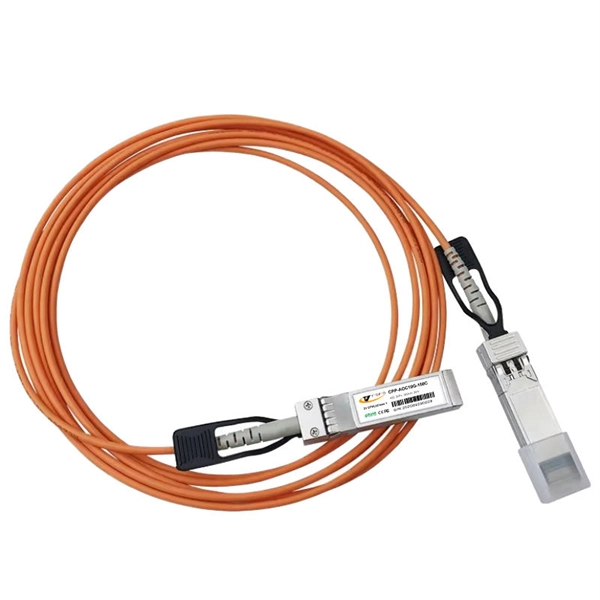
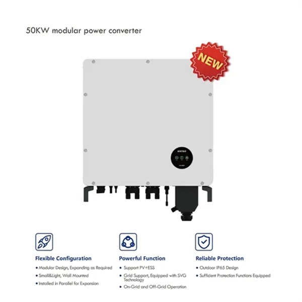
This article explores the current trends, innovations, and market insights surrounding relay protection, focusing on tools like the secondary injection test set, three-phase relay test set, and single-phase relay test set. Relay protection systems are essential in maintaining the safety and reliability of modern electrical grids. These clean energy sources, connected through inverters and flexible transmission systems, are transforming traditional grids based on synchronous generators into more flexibl cant challenges to system stability. Nowhere is that clearer than in the challenge to. The protection relay is the silent sentinel of the electrical grid, a device that spends most of its life waiting for a fraction of a second where its intervention is required to save millions of dollars in equipment and prevent injury to personnel. For over a century, these devices have evolved. Understanding Protective Relays: Backbone of Grid Security Protective relays are devices designed to detect faults, anomalies, or abnormal conditions in electrical systems and trigger circuit breakers to isolate problematic sections.
[PDF Version]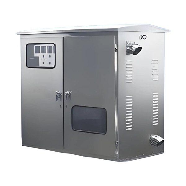
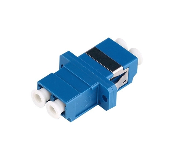
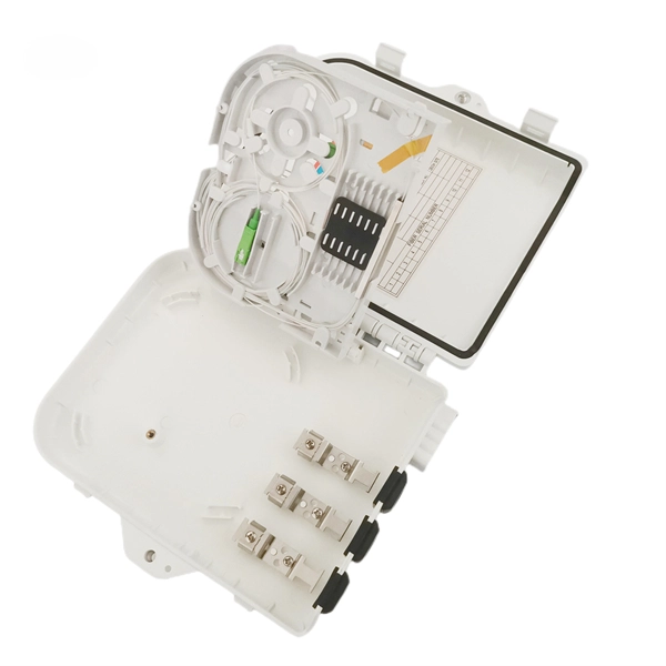
Patch cables connect the splitter to the equipment, so it's essential to choose high-quality cables for reliable performance. The input/output configuration (1×2, 1×4, etc. A fiber-optic splitter, also known as a beam splitter, is based on a quartz substrate of an integrated waveguide optical power distribution device, similar to a coaxial cable transmission system. The optical network system uses an optical signal coupled to the branch distribution. One component makes PON deployment scalable and efficient: the fiber optic splitter.
Side clearance: There should be a minimum of 30 inches of clearance from the sides of all electrical equipment, but in no case less than the width of the equipment itself. This is referred to as the side-to-side working space. NEC Article 408 covers switchboards, switchgear, and Panelboards installation and applications. Walk into almost any garage or basement, and you'll see one of the NEC's most common red tags waiting to happen. It's been a. The National Electrical Code establishes electrical panel clearance requirements to ensure that the panel operates safely and has a clear space in front of it in case of an emergency. The panel should also have space for efficient airflow, as it may overheat.
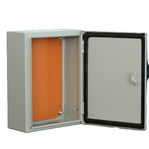
The distribution box is composed of independent single box connected by bolts, and the bottom of the box is composed of 3mm aluminum zinc coated steel sheet solid welding plate at the front and back. Reasons for material selection: The strength and corrosion resistance of steel plate make it a common material for the box of the distribution box, and its good conductivity also. The distribution box is a low-voltage distribution device composed of switchgear, measuring instruments, protective appliances and auxiliary equipment assembled in closed or semi closed metal cabinets or panels according to the electrical wiring requirements. During normal operation, the circuit. The distribution box is divided into power distribution box and lighting distribution box, which is the last level equipment of the distribution system. The main functions are "power.
Contact us for competitive quotes on any of our power communication and smart grid products
Get a Quote