
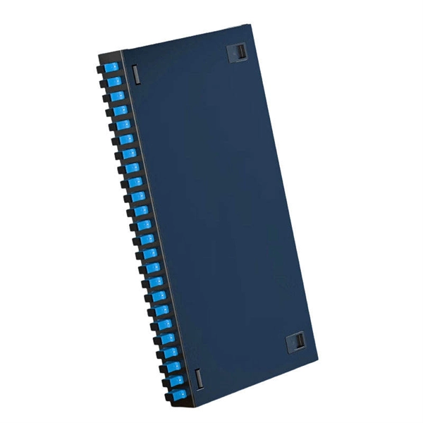
Upper incoming line, lower outgoing line, main circuit on the left, control circuit on the right, horizontal and vertical. The exposed laying can take the sheath line, or through the pipe and trunking. A distribution board or distribution box is where the main power supply is distributed to multiple loads. And all the switching and protective devices are installed in the. Exposed electrical wires present a serious hazard, creating immediate risks of electric shock and fire from short circuits or arcing. However, the key to. Connection method: Each switch takes a wire from the incoming point and connects it to the incoming end of the switch, or uses parallel connection to reduce the difficulty of wiring.
What Is a Distribution Box?A distribution box, also known as a power distribution unit, is a critical component in any electrical system. It is the control center fo.
What Is a Distribution Box?A distribution box, also known as a power distribution unit, is a critical component in any electrical system. It is the control center fo.
26 mm 2 (10 AWG) ground wire must be used, and in all other markets a 6 mm 2 must be used. Today, we're diving deep into the world of distribution box grounding, breaking down the standards, and shining a light on those sneaky mistakes that even experienced electricians sometimes make. Whether you're a seasoned pro or just starting out, this comprehensive guide will give you practical. Metal raceways, cable trays, cable armor, cable sheath, enclosures, frames, fittings, and other metal noncurrent-carrying parts that are to serve as grounding conductors, with or without the use of supplementary equipment grounding conductors, shall be effectively bonded where necessary to ensure. 1. Which circuit conductor must be grounded. The characteristics of the. Section 250. 4 states the general requirements for grounding and bonding of electrical systems for both grounded and ungrounded systems. For grounded systems, the NEC requires you to perform all of the following: electrical system grounding, electrical equipment grounding, electrical equipment. The National Electrical Code (NEC) provides clear guidelines for ground wire sizing through Table 250.
[PDF Version]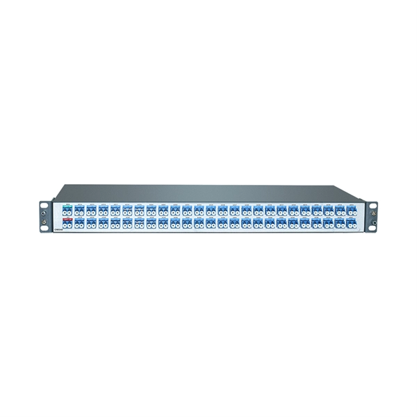
Due to their exposure to the open air because of the cable trays, the wires contained within need a very durable outer covering. The regulations dictate that the cables must either be Type TC (also known as Tray Rated) or must be metal-armored (Type MC). Can any cable be used in a tray? The short answer is no. Cable trays are a support system for electrical cables, power, signal, and communication and optical fiber cables. NEC section 300-8 does not permit. According to the 2005 National Electrical Code® (NEC), a cable tray system is “ unit or assembly of units or sections and associated fittings forming a structural system used to securely fasten or support cables and raceways. ” Cable trays support cable across open spans in the same manner that. Cable tray systems provide a safe, organized, and flexible method for supporting insulated conductors and cables in commercial and industrial electrical installations.
[PDF Version]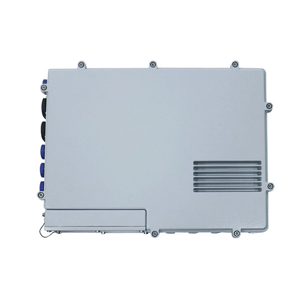
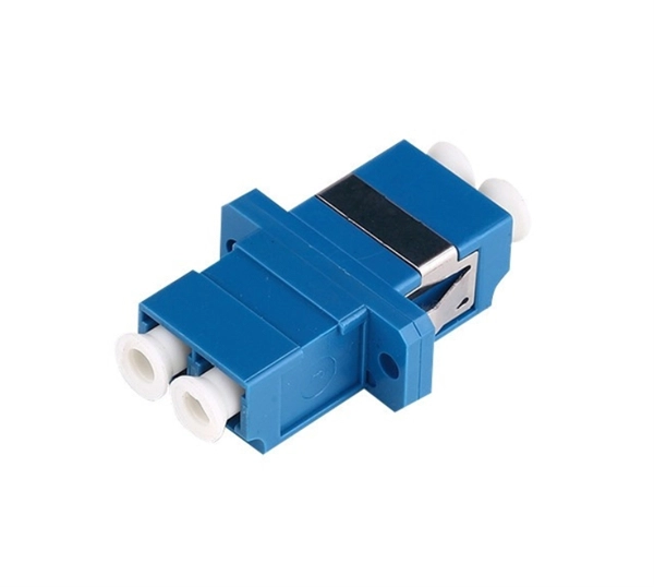
Choose patch cables (SC-SC, FC-FC, SC-FC) based on the type of connectors at the splitter and distribution box. Fixed power distribution equipmen t manufactured by Union Connector includes patch panels, connector strips, specification type outlet boxes and pigtail boxes. These products are designed for overhead or wall mounting in theatrical or studio applications. Union Connector builds these devices to. Create tidy rows of wire connections that you can identify, test, and adjust on the spot Route electricity within switchboards and battery banks; also known as bus bars Expand and reconfigure a data network when space inside your enclosure is limited Distribute electricity from a single power. Ethernet patch panels make the connection between field cabling and control cabinet cabling quick and easy. A standard Ethernet patch cable. At MTX Electrical and Engineering we pride ourselves on providing those in the theatre and stage industries with premium electrical goods that are durable to stand up to repeated use in testing environments.
[PDF Version]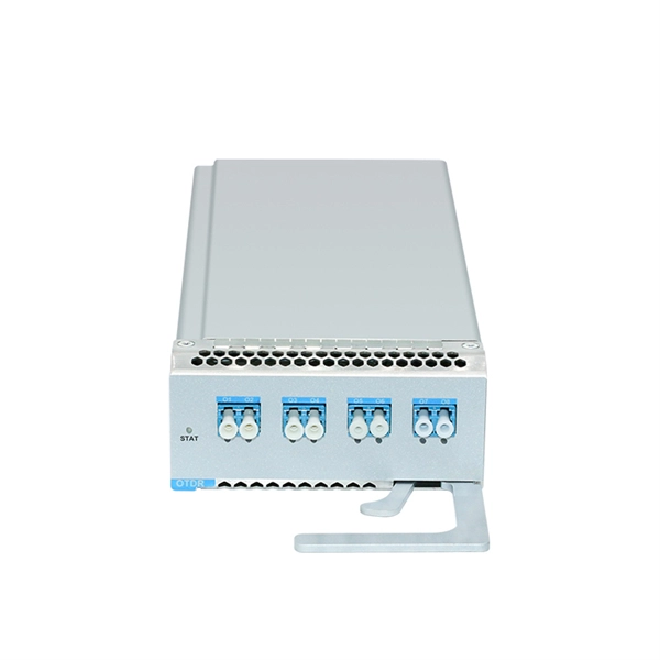
Strain relief bar (SRB) is a cable management solution, which in most cases, attaches to the back of the rails via the strain relief bar brackets. It also helps you arrange interface cables in such a way that the power modules, fan assembly, and air filte n for the Cisco 10005 router. The cable management bracket enables you to route the cables outside the router and away from the Routing Engines and LMICs. Figure. These rack types are broken down in Table 2 into 4-post and 2-post styles. 4-post rack types contain vertical mounting flanges with either square-hole, unthreaded round-hole, or threaded round-hole designs as part of the rack and rail interface. This washer is not installed. The following guidelines provide cabling information for installing, migrating, relocating, or upgrading your system: Position drawers in racks to allow enough space, where possible, for cable routing on the bottom and top of the rack, and between drawers. Shorter drawers must not be placed between.
[PDF Version]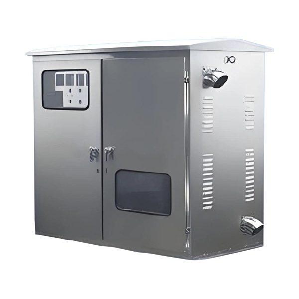
Patch cables connect the splitter to the equipment, so it's essential to choose high-quality cables for reliable performance. The input/output configuration (1×2, 1×4, etc. A fiber-optic splitter, also known as a beam splitter, is based on a quartz substrate of an integrated waveguide optical power distribution device, similar to a coaxial cable transmission system. The optical network system uses an optical signal coupled to the branch distribution. One component makes PON deployment scalable and efficient: the fiber optic splitter.
Contact us for competitive quotes on any of our power communication and smart grid products
Get a Quote