
Instantaneous overcurrent protection is where a protective relay initiates a breaker trip based on current exceeding a pre-programmed “pickup” value for any length of time. The protection operates with a definite time characteristic. The protection offers two. This paper focuses on using the threshold current and voltage to reduce the time of delay and trip time of the instantaneous overcurrent relay protection for a 330 kV transmission line. The wavelet transforms toolbox from MATLAB and a Simulink model were used to design the model to detect the. to carry continuously without tripping.
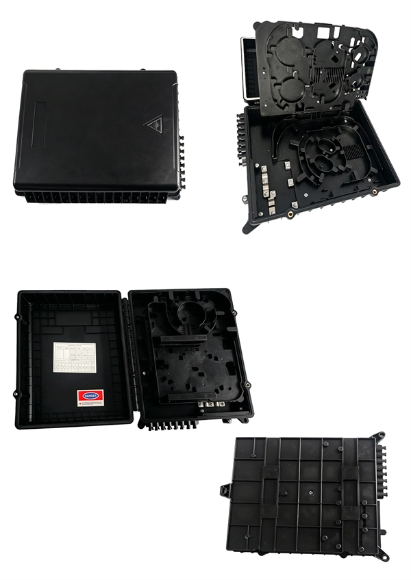
What Is a Distribution Box?A distribution box, also known as a power distribution unit, is a critical component in any electrical system. It is the control center fo.
The TFT (Thin-Film Transistor) screens used in relay protection applications play a pivotal role in providing operators with clear, actionable information in real-time. Its modular design and powerful DIGSI 5 engineering tool provide tailored solutions. This reference design showcases a two-dimensional (2-D) Qt graphical user interface (GUI), which is typical for. presentation of protection and control relaying. The report will identify methodology behind these practices, present issues raised by the integration of microprocessor relays and the internal logic and external communication configurations, ying. The first numerical relays were released in 1985.

Remove the CPU module from the relay housing and set aside. Be certain to align the printed circuit board with the card guides in the housing. Always use antistatic bags for transporting modules Remove AC power and DC power from the PCD before removing, installing or wiring any of the PCD modules. Consult. What are the steps for safely removing and reinstalling a PLC CPU module? Safe removal and reinstallation of a PLC CPU module requires strict adherence to proper procedures to prevent equipment damage, data loss, or safety hazards. Consult the most recent PCD Instruction Book for details on programming the new CPU to suit your requirements. 0 or Modbus ASCII communications, protocol documentation is available. 1. 1 INTRODUCTION TO THE UR The GE Universal Relay (UR) series is a new generation of digital, modular, and multifunction equipment that is easily incorporated into automation systems, at both the station and enterprise levels. In particu-lar, one will find: General information with regard to design, configuration, and operation of SIPROTEC 4 devices are set out in the SIPROTEC 4 System Description /1/.
[PDF Version]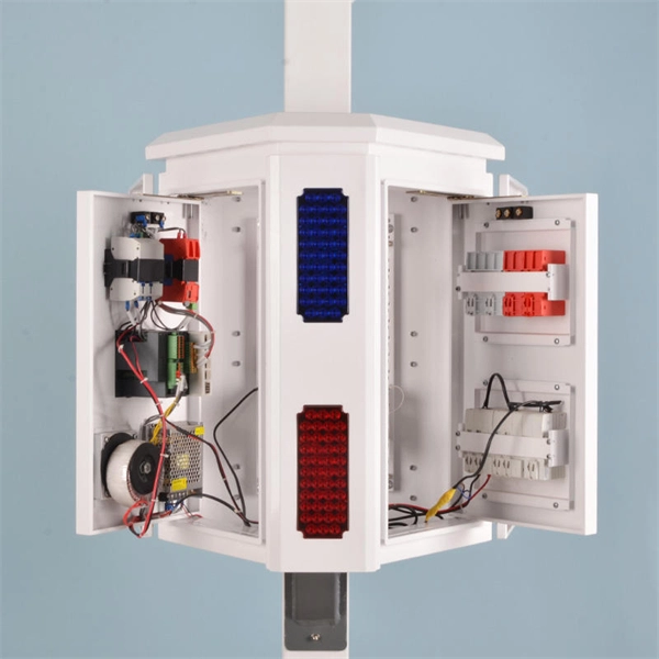
The article provides an overview of protective relaying principles and their applications for high-voltage power system components. It covers the protection methods for generators, transformers, buses, and transmission lines using various relay types to detect and isolate faults efficiently.
The metal box of the distribution box, the electrical installation board, and the metal base and casing of the electrical appliances in the box must be grounded. The protective neutral wire should be reliably connected through the terminal board. Are you expecting any of those 6 switches will require a neutral connection? @RobertChapin Does not. But it does require panelboard with a neutral that has more than 10 percent of its overcurrent devices rated 30 amperes or less to be protected against overcurrent by a device that has a rating not greater than that of the panelboard. It includes isolator, RCCB (Residual current circuit breaker) or RCD (Residual-current device) devices, protective fuses or MCB's (Miniature Circuit Breaker).

This article explores the current trends, innovations, and market insights surrounding relay protection, focusing on tools like the secondary injection test set, three-phase relay test set, and single-phase relay test set. able sources such as wind and solar. These clean energy sources, connected through inverters and flexible transmission systems, are transforming traditional grids based on synchronous generators into more flexibl cant challenges to system stability. A big difference between conventional electromechanical and static relays is how the relays are wired. Numeric. IEEE/IAS/I&CPSD Protection & Coordination WG Chair Jacobs Canada, Calgary, AB rasheek. com IEEE Southern Alberta Section PES/IAS Joint Chapter Technical Seminar - November 2016 Protective Relays - Technical Seminar Nov 2016 - Copyright: IEEE 2 Abstract: Protective relays and devices. At the core of a modern substation lies the protection relay: an intelligent electronic device (IED) that plays a critical role in maintaining the stability of the power grid by continuously monitoring voltage, current, frequency, and phase angle.
[PDF Version]
Phase comparison Technique (PCT) is a type of protection by which the quantities are conveyed through communication channels rather than wired interconnections of the relay input devices and it detects both phase and ground faults simultaneously. The phase comparison relaying principle is a line of differential relaying that compares the phase angles of the current entering one terminal of a transmission line with the phase angles of the current entering all the remote terminals of the same line. During normal conditions or through faults the currents. Why are seal-in and 52a contacts used in the dc control scheme? In a typical feeder OC protection scheme, what does the residual relay measure? Questions? 00000001 00000101 00001001 00100100 10010000 :. 51P1P Pickup 51P1C Pickup Type 51P1TD Time Dial 51P1RS Electromechanical Reset? (Y / N) 51P1CT. protective system, Components of Protection System. Sequence Components and Fault Analysis: sequence impedance, fault calculations, Single line to ground fault, Line to ground fault with Zf, Faults in Power syst ional relays, Distance relays, Differential relays. Those categories are directional comparison and phase comparison.
[PDF Version]
The IEC 61439-1 sets the thermal limit in busbars working at the maximum working load. Here, 140°C (which is 105K over the ambient temperature of 35°C) is the upper safe temperature limit. Continuous, real-time busbar temperature monitoring and hot spot detection for MV & HV switchgear, substations and power plants — EMI-immune, calibration-free, fully SCADA-integrated. Thermal monitoring locations include: Eaton Exertherm CTM solution for MV switchgear. Standards mandate that busbars, when carrying their rated continuous current for extended periods, must not experience excessive temperature rise.
This leakage current is measured in milliamps 'mA' (1/1000 amp) and if the leakage current reaches a pre-determined level, usually 30 mA '0. 03 A' the device will operate and isolate the supply from the circuit. In addition to fault protection (protection in cases of indirect contact), residual current protective devices with rated residual currents up to 30 mA also provide “additional protection” in cases of direct contact. Fires caused by ground-fault currents can also be prevented at a very early stage. Subsequently, new types of RCD have been developed. This article. RCDs, or Residual Current Devices, are designed to monitor the electrical current flowing in a circuit and automatically disconnect the power supply if it detects an imbalance between the live and neutral conductors.
Contact us for competitive quotes on any of our power communication and smart grid products
Get a Quote