
This article provides a comprehensive framework that governs various aspects of cable tray installations, including the types of cables that are deemed acceptable for use, requirements for grounding and bonding, and stipulations regarding tray fill capacity. Cable tray may be used as the Equipment Grounding Conductor (EGC) in any installation where qualified persons will service the installed cable tray system. Each method must be selected based on environment, standards, and system type. Grounding. Cable tray systems have become an essential component in the infrastructure of modern commercial buildings, smart offices, data centers, and various industrial facilities. These systems provide an efficient and adaptable solution for managing a wide range of cables, including power cables, control. Understanding cable‐tray e arthing comes early in the 18th-Edition module of the electrician courses at Elec Training Birmingham.
[PDF Version]
Attach a ground wire from one of the threaded studs (A) at the bottom of the housing, to the mounting plate (B). This helps to reduce the potential difference that exists between conductive parts and the earth. Equipment Protection: Grounding protects substation. Power from factory ground must be installed by a qualified electrician. Each DISTRIBUTION BOX and controller must be grounded. 26 mm 2 (10 AWG) ground wire must be used, and in all other markets a 6 mm 2 must be used. It cannot be used or copied for any other. Any engineer dealing with power supply networks needs to understand the basic principles of grounding system design and its role in ensuring safety of equipment and personnel.

This article presents a case study of the struggles of South Sudan, the newest country to develop a new electricity grid, and the strategic choices it faces in a post-conflict situation. In addition to the energy tri.
26 mm 2 (10 AWG) ground wire must be used, and in all other markets a 6 mm 2 must be used. Today, we're diving deep into the world of distribution box grounding, breaking down the standards, and shining a light on those sneaky mistakes that even experienced electricians sometimes make. Whether you're a seasoned pro or just starting out, this comprehensive guide will give you practical. Metal raceways, cable trays, cable armor, cable sheath, enclosures, frames, fittings, and other metal noncurrent-carrying parts that are to serve as grounding conductors, with or without the use of supplementary equipment grounding conductors, shall be effectively bonded where necessary to ensure. 1. Which circuit conductor must be grounded. The characteristics of the. Section 250. 4 states the general requirements for grounding and bonding of electrical systems for both grounded and ungrounded systems. For grounded systems, the NEC requires you to perform all of the following: electrical system grounding, electrical equipment grounding, electrical equipment. The National Electrical Code (NEC) provides clear guidelines for ground wire sizing through Table 250.
[PDF Version]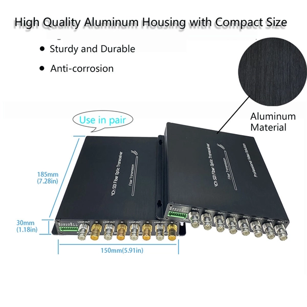
26 mm 2 (10 AWG) ground wire must be used, and in all other markets a 6 mm 2 must be used. Grounding is a mechanism to protect distribution equipment and people under normal operating conditions, abnormal operational (overcurrent and overvoltage) responses, and hazardous conditions such as shocks. The multiplicity of the ground locations is considered to make the overall impedance to remote earth low enough. Arresters are more effective with a low local impedance. Seevers. Whether you're a seasoned pro or just starting out, this comprehensive guide will give you practical insights into proper grounding techniques, with a special focus on how selecting quality materials from a reliable building material supplier impacts your entire system's safety and longevity. Each DISTRIBUTION BOX and controller must be grounded. Grounding of the units: Attach a ground wire from one of. Additional rules for the grounding and bonding of industrial control panels include the sizing of ground conductors and the conditions that dictate when power supplies and transformers must be grounded.
[PDF Version]
Ungrounded: There is no intentional ground applied to the system-however it's grounded through natural capacitance. This decreases the current at the fault and limits voltage across the arc at the. Secondary equipment grounding refers to connecting the secondary equipment (such as relay protection and computer monitoring systems) in power plants and substations to the earth via dedicated conductors. It covers the protection methods for generators, transformers, buses, and transmission lines using various relay types to detect and isolate faults efficiently. The. Operating Principles and Relay Construction: Electromagnetic relays, thermal relays, static relays, microprocessor based protective relays Time-current characteristics, current setting, over current protective schemes, directional relay, protection of parallel feeders, protection of ring mains. While ground-fault protective schemes may be elaborately developed, depending on the ingenuity of the relaying engineer, nearly all schemes in common practice are based on one or more of the methods of ground-fault detection discussed in this article. Therefore, they feed earth fault current to the fault.
[PDF Version]Contact us for competitive quotes on any of our power communication and smart grid products
Get a Quote