
the redundant operation of aggregation/distribution switches, increases the reliability of the aggregation layer, and connecting the relevant access switches to two different network nodes in the aggregation/distribution layer ensures an extremely. Stacking, i. in 3 switches, one acts as Master - it has all config Layer 2 and Layer3 (rest 2 switch act as a member do not hold any config) Once the master switch failed next slave switch becomes master electing stat functioning as expected. you can. The S5860-20SQ 24-port 10Gb Ethernet layer 3 switch features 20x 1G/10G downlinks, 4x 10G/25G SFP28 and 2x 40G QSFP+ (can be split into 4x 10G SFP+) uplinks that all support virtual stacking. This managed enterprise switch adopts cutting-edge Broadcom chips to deliver 760 Gbps switching capacity. Switch stacking is a method of binding multiple switches so that they can act as a single switch. This method is applicable on access layer switches. They require a strategy to prevent this sort of disruption from occurring again. Any suggestions? Perhaps break it up into. Stacking, i.
[PDF Version]
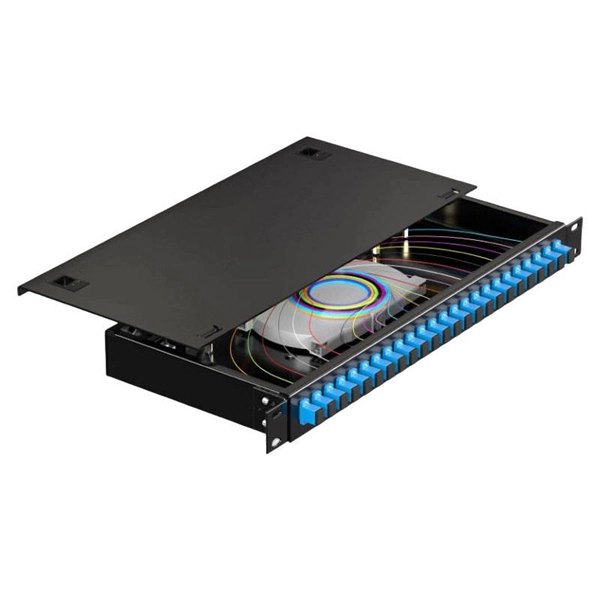
The Aggregation Layer connects the Core Layer with Access Layer for data collection and distribution, typically by way of convergence layer switches that possess high bandwidths with minimal latency lags and bandwidth-limited latency settings; such switches serve to connect various. The Aggregation Layer connects the Core Layer with Access Layer for data collection and distribution, typically by way of convergence layer switches that possess high bandwidths with minimal latency lags and bandwidth-limited latency settings; such switches serve to connect various. MLAG (Multi-chassis Link Aggregation Group or Multi-chassis LAG) is a method to form the link aggregation group (LAG) among multiple devices for redundancy — When one of the switches fails, the system can still work. 1AX-2008 standard that defined LAG does not mention. An aggregation switch is a network device that consolidates traffic from multiple access switches, wireless access points, or other edge devices and forwards it to core switches or routers. By bundling multiple network connections into a single high-bandwidth link, aggregation switches help. Provides 1G, 2.
[PDF Version]
Since V200R011C10, S5720HI series switches can set up stacks in service port stacking mode using dedicated stack cables. When 10GE SFP+ optical ports are used as stack ports, a switch supports a maximum of two logical stack ports, and each logical stack port supports a maximum of four stack member ports. Each switch can. This article summarizes several solutions for using optical modules with switches and common problems encountered during usage, along with specific solutions. Huawei S5720-32P-EI-AC Switch II. Posted by:XPONSHOP As we know, switch stacking deployment has some special requirement or limitation, this blog will share the software version and model requirement in detail on Huawei S Series Switches stack. Switch stacking is the process of combining multiple switches into a logical device that participates in data forwarding as a whole, in order to expand the number of ports, simplify networking, increase reliability, and extend the system's processing power and bandwidth. Moduletek Labs takes Huawei. Switch stacking is a cornerstone of modern network design, enabling simplified management, improved redundancy, and scalable bandwidth.
[PDF Version]
In this guide, we will learn how to control an LED using a simple SPST (Single Pole Single Throw) switch with the 8051 microcontrollers. Combining switches and LEDs in Arduino projects can create interactive and engaging applications. You can make the. I wire single-color LEDs by connecting VCC to a 12V power supply, GND through a switch, and OUTPUT to complete the loop. Then I run the OUTPUT through the switch. The wiring for the LED is very similar to when we first. Pulse Width Modulation (PWM) is a technique for controlling the brightness of LEDs by varying the duty cycle of a square wave.
The PoE switch supplies power, the Ethernet cable carries both power and data, and the device receives everything through one connection. This is the most straightforward PoE configuration and is commonly used for powering devices like access points, cameras, and VoIP. Explains how PoE-capable switch identify the power requirement and how PoE works on a switch. ) via Ethernet cables, enabling them to communicate over a Local Area Network (LAN). Unlike simple hubs that broadcast data to all ports, switches create a direct. Therefore, everyone is concerned about whether PoE switches will affect speed. PoE calculation is done during initial link negotiation. 3af standard, which specifies the maximum power delivered over Ethernet cables. 4 watts of power per port, while PDs can consume up to 12.
Three modes, Mode A, Mode B, and 4-pair mode, are available. (In the standard, these are discussed as two Modes, with the term 4-pair mode for both simultaneously.)OverviewPower over Ethernet (PoE) describes any of several or systems that pass along with data on cabling. This allows a single cable to provide both a data connection. There are several common techniques for transmitting power over Ethernet cabling, defined within the broader standard since 2003. The three t. The original PoE standard, IEEE 802.3af-2003, now known as Type 1, provides up to 15.4 W of power (minimum 44 V DC and 350 mA) on each port. Only 12.95 W is guaranteed to be available at the powered device as s.
Contact us for competitive quotes on any of our power communication and smart grid products
Get a Quote