
The Aggregation Layer connects the Core Layer with Access Layer for data collection and distribution, typically by way of convergence layer switches that possess high bandwidths with minimal latency lags and bandwidth-limited latency settings; such switches serve to connect various. The Aggregation Layer connects the Core Layer with Access Layer for data collection and distribution, typically by way of convergence layer switches that possess high bandwidths with minimal latency lags and bandwidth-limited latency settings; such switches serve to connect various. MLAG (Multi-chassis Link Aggregation Group or Multi-chassis LAG) is a method to form the link aggregation group (LAG) among multiple devices for redundancy — When one of the switches fails, the system can still work. 1AX-2008 standard that defined LAG does not mention. An aggregation switch is a network device that consolidates traffic from multiple access switches, wireless access points, or other edge devices and forwards it to core switches or routers. By bundling multiple network connections into a single high-bandwidth link, aggregation switches help. Provides 1G, 2.
[PDF Version]
Since V200R011C10, S5720HI series switches can set up stacks in service port stacking mode using dedicated stack cables. When 10GE SFP+ optical ports are used as stack ports, a switch supports a maximum of two logical stack ports, and each logical stack port supports a maximum of four stack member ports. Each switch can. This article summarizes several solutions for using optical modules with switches and common problems encountered during usage, along with specific solutions. Huawei S5720-32P-EI-AC Switch II. Posted by:XPONSHOP As we know, switch stacking deployment has some special requirement or limitation, this blog will share the software version and model requirement in detail on Huawei S Series Switches stack. Switch stacking is the process of combining multiple switches into a logical device that participates in data forwarding as a whole, in order to expand the number of ports, simplify networking, increase reliability, and extend the system's processing power and bandwidth. Moduletek Labs takes Huawei. Switch stacking is a cornerstone of modern network design, enabling simplified management, improved redundancy, and scalable bandwidth.
[PDF Version]
the redundant operation of aggregation/distribution switches, increases the reliability of the aggregation layer, and connecting the relevant access switches to two different network nodes in the aggregation/distribution layer ensures an extremely. Stacking, i. in 3 switches, one acts as Master - it has all config Layer 2 and Layer3 (rest 2 switch act as a member do not hold any config) Once the master switch failed next slave switch becomes master electing stat functioning as expected. you can. The S5860-20SQ 24-port 10Gb Ethernet layer 3 switch features 20x 1G/10G downlinks, 4x 10G/25G SFP28 and 2x 40G QSFP+ (can be split into 4x 10G SFP+) uplinks that all support virtual stacking. This managed enterprise switch adopts cutting-edge Broadcom chips to deliver 760 Gbps switching capacity. Switch stacking is a method of binding multiple switches so that they can act as a single switch. This method is applicable on access layer switches. They require a strategy to prevent this sort of disruption from occurring again. Any suggestions? Perhaps break it up into. Stacking, i.
[PDF Version]
Connect Switch with a corresponding fiber device through a fiber cable, or connect with a Media Converter and change to electrical signal for output. Users could choose to use the SFP fiber port or electrical port of the Switch according to different conditions;Equipped with eight SFP+ ports, two additional SFP28 ports and one RJ45 console port for configuration. With AXIS D8308 Fiber Aggregation Switch you can connect multiple Axis devices using fiber midspans over long distances. Simply put, it defines how network. This article reviews essential features as well as benefits and technical specifications associated with an 8 port sfp optical switch, thus giving you a complete idea of how it works in modern networking environments. Whether you work as an IT professional or have an interest in technology only. This SR8 multimode, parallel, 8-channel transceiver uses two, 4-channel MPO-12/APC optical connectors at 400Gb/s each. The parallel multimode, short reach 8-channel (2xSR4) uses 100G-PAM4 modulation and has a maximum fiber reach of 50-meters using 8 multimode fibers. Cisco Catalyst 1000 Series switches provide support for the.
[PDF Version]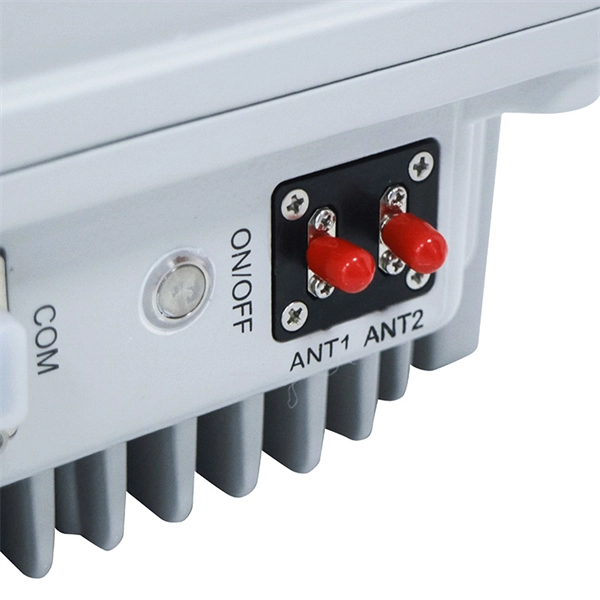
In this guide, we will learn how to control an LED using a simple SPST (Single Pole Single Throw) switch with the 8051 microcontrollers. Combining switches and LEDs in Arduino projects can create interactive and engaging applications. You can make the. I wire single-color LEDs by connecting VCC to a 12V power supply, GND through a switch, and OUTPUT to complete the loop. Then I run the OUTPUT through the switch. The wiring for the LED is very similar to when we first. Pulse Width Modulation (PWM) is a technique for controlling the brightness of LEDs by varying the duty cycle of a square wave.
Enables IP routing between VLANs, subnets, and security zones, with advanced routing protocols. Modular chassis or stackable designs make it easy to scale as your network . A core switch is a high-capacity, high-performance Layer 3 switch positioned at the physical backbone of an enterprise network. Engineered to aggregate massive volumes of data from distribution switches, it provides ultra-low latency and maximum throughput to ensure uninterrupted routing and packet. It's more than just a switch; it's the central nervous system of your network infrastructure. A core switch operates at the italic core layer italic of a hierarchical network design, typically handling a massive volume of data traffic. Enable AI-ready 800G infrastructure for data centers of any size. 488 Mpps) + (Number of 100-Megabit Ports × 0.
Directional couplers are multiple-waveguide couplers used for codirectional coupling. They can be used in many different applications, including power splitters, optical switches, wavelength filters, and polarization selectors. We consider in this tutorial two-channel directional couplers, which. Mode division multiplexing (MDM) has provided a new trend in high capacity optical transmission systems.
Three modes, Mode A, Mode B, and 4-pair mode, are available. (In the standard, these are discussed as two Modes, with the term 4-pair mode for both simultaneously.)OverviewPower over Ethernet (PoE) describes any of several or systems that pass along with data on cabling. This allows a single cable to provide both a data connection. There are several common techniques for transmitting power over Ethernet cabling, defined within the broader standard since 2003. The three t. The original PoE standard, IEEE 802.3af-2003, now known as Type 1, provides up to 15.4 W of power (minimum 44 V DC and 350 mA) on each port. Only 12.95 W is guaranteed to be available at the powered device as s.
In this video, I show how to use a MOSFET as a touch-activated ON/OFF switch to power a laser diode — no buttons, no mechanical contacts. Just a simple, clean and smart circuit. more Control a laser module with just a fingertip!I am quite new to the Arduino business and up until now managed to create a Hexapod robot from a kit based on the Arduino Mega 2560, add Computer Vision and let him crawl around to find target objects. Now I want to destroy the target (in this case. So I just bought a laser diode with. They typically have three input pins: VCC (power supply), GND (ground), and SIG (signal). Other modules include only two pins: VCC (power supply) and GND. Another very popular option and sometimes cheaper is to buy/recycle a laser pointer directly and take advantage of the electronics, the head, and the casing, which integrated into a project look very good. We can find pointers of all colors for 1.
[PDF Version]
An uplink port generally means a port used that connects toward the core of the network. In this particular usage, the switch's downlink ports are dual speed copper ports. RJ45 ports serve access-layer copper connections; SFP/SFP+ ports enable flexible 1G/10G uplinks; SFP28 delivers 25G for modern data centers; QSFP+ and QSFP28 support high-density 40G/100G spine–leaf. So, the uplink port connects the switch to other switches or “higher” layer routers. Switch normal ports, also known as. The SFP port is commonly found on Gigabit Ethernet switches and is primarily used for fiber optic device connections or for uplinking 1G switches to aggregation/core layer devices, providing higher-bandwidth links. Switch port type should be configured according to the requirement considering the factors like network architecture, speed and. Cisco switch ports are categorized by their physical hardware interfaces (such as RJ45 copper, fiber-optic SFP uplinks, and console ports), their bandwidth speed capacities (Gigabit, 10G, 100G), and their logical operating modes.
[PDF Version]Contact us for competitive quotes on any of our power communication and smart grid products
Get a Quote