
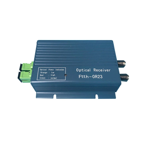
Optical testing involves measuring the laser diode's output power, wavelength, spectrum, and beam profile. These parameters are critical for laser diode applications that require precise and stable optical performance, such as fiber-optic communication systems and optical sensors. 📦 For purchasing, use the RP Photonics Buyer's Guide for laser diode testing. What is Laser Diode Testing? Why is laser. The light-current-voltage (L-I-V) sweep test is a fundamental measurement that determines the operating characteristics of a laser diode (LD). The versatile LIV Test System combines source and measurement. This comprehensive guide dives deep into the methods and considerations involved in testing laser diodes using a multimeter, providing practical insights and actionable steps for ensuring accurate results and preventing costly errors.
FOA procedures, such as OFSTP-7 (single-mode) and OFSTP-14 (multimode), align with TIA and IEC standards. Fiber Optic Testing Testing is used to evaluate the performance of fiber optic components, cable plants and systems. As the components like fiber, connectors, splices, LED or laser sources, detectors and receivers are being developed, testing confirms their performance specifications and helps. ondition of the cabling system and its components with an op cal time domain reflectometer (OTDR). The condition of the fibre end fac g with an OLTS and an OTDR and have obtained a certificate as proof thereof shall execute the tests. 11 Optical Fiber Systems Subcommittee and published in September, 2022. They describe how to set a '0 dB' reference, control mode power distribution, and use proper wavelengths.
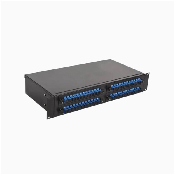
3‑E “Optical Fiber Cabling and Components Standard” was developed by the TIA TR‑42. The International Electrotechnical Commission (IEC) and the Telecommunications Industry Association (TIA) create detailed rules for fiber optic components, manufacturing, and testing. Scope: This Standard specifies performance, transmission, and test and measurement requirements for premises optical fiber cable. International standards for optical connectors are developed by the International Electrotechnical Commission (IEC). Fiber optic assemblies are unforgiving. Unlike copper wire harnesses where a slightly imperfect crimp might still conduct electricity, a contaminated fiber end face or improper splice can completely block light transmission. These standards ensure interoperability across manufacturers, regions, and applications.
Test the Repair: Before re-installing the harness, test the repaired section with a multimeter for continuity and correct resistance. A faulty pigtail can lead to anything from intermittent malfunctions to complete system failure, even posing a significant safety hazard. It provides a plug-and-play repair solution that restores OEM fit, seal, and electrical reliability. Pigtails are. A single defect in a flange—whether a microscopic crack in the forging, a deviation in bolt hole alignment, or an improper surface finish—can lead to gasket blowout, fugitive emissions, or structural failure under high pressure. For EPC contractors, QA/QC engineers, and procurement managers. from spring clip the spring the fixed clip clip to compress, side). This allows fixed releases clip then wing peater so from •should Always remember be required. Common problems include rusted connectors, damaged. Is the failure symptom that no data traffic can get from one side of the repeater to the other, or that a hard error such as a beaconing condition is present on the ring? Go to page 9. For some of the troubleshooting steps mentioned on.
[PDF Version]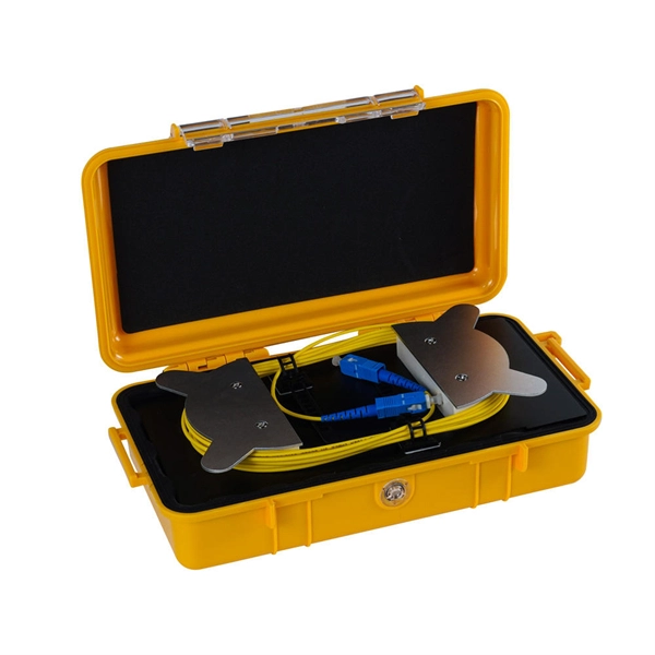
The loss value of a pigtail connector and its associated splice with matching mode field diameters should not exceed 0. Pigtail traces for all. at system. Corning recommends that all fiber optic systems be tested to a minimum set of standards. So, you drop everything and i vestigate. FOA standards align with IEC and TIA, giving you clear steps to earn trusted certification. No part of this book may be reproduced or utilized in any form or means, electronic or mechanical, including photocopying, recording, or by any information storage and retrieval system, without pe n optical fiber to a distant receiver. The electrical signal is. To be able to judge whether a fiber optic cable plant is good, one does a insertion loss test with a light source and power meter and compares that to an estimate of what is a reasonable loss for that cable plant.
In , a busbar (also bus bar) is a metallic strip or bar, typically housed inside,, and for local high current power distribution, transmission, or switching substations. They are also used to connect high voltage equipment at electrical switchyards, and low-voltage equipment in. They are generally uninsulated, and have sufficient stiffness to be s.
Relay protection is essential to ensure the stability, reliability, and safety of electrical power systems. Generator protection covers: phase-to-phase short circuits in stator windings, stator ground faults, inter-turn short circuits in stator windings, external short circuits, symmetrical overload, stator overvoltage, single- and double-point grounding in the excitation circuit, and loss of excitation. Numerical relays are based on the use of microprocessors. A big difference between conventional electromechanical and static relays is how the relays are wired. At the core of a modern substation lies the protection relay: an intelligent electronic device (IED) that plays a. IEEE/IAS/I&CPSD Protection & Coordination WG Chair Jacobs Canada, Calgary, AB rasheek. In HV (High Voltage) and MV (Medium Voltage) substations, relay protection safeguards critical assets such as transformers, circuit breakers, and lines.
[PDF Version]
Cable trays provide a strong mechanical support system while maintaining accessibility for inspection, maintenance, and future expansion. This article records the installation process of cable trays carried out in the substation, highlighting procedures, materials, safety. Installing a 35KV substation cable tray correctly is important. Are you worried about mistakes, safety, or just how to get started? I know the feeling. Getting this kind of work right, especially with high-voltage equipment, needs a clear, step-by-step plan. This guide breaks down the whole process. maintain spacing or to keep cables in place when the tray is ect the minimum bend ra-dius for cables as they exit the bottom of the cable tray.
Contact us for competitive quotes on any of our power communication and smart grid products
Get a Quote