
The ATTO Celerity FC-642E leverages two next-generation storage technologies – PCIe 4. 0 interconnect and Gen 7 Fibre Channel to provide an advanced storage connectivity solution with high performance, intelligence and scalability. Unleash the full potential of your storage infrastructure with high-performance Fibre Channel HBAs from ATTO. Engineered to give you the edge, Celerity HBAs. ATTO Celerity Fibre Channel HBAs deliver the fastest data throughput available for today's most demanding Storage Area Network environments. Included with all ATTO HBAs are.
A fiber splice tray is typically a tray or panel with slots or compartments where individual fiber optic cables can be neatly arranged and spliced together. The rule is to coil the fiber once after each splicing and heat shrinking of one or several optical fibers in fiber optic sleeve or optical fibers in a branch direction optical cable. Advantages: It avoids the confusion of optical fibers between fiber protection sleeve or between different branch. Fiber cable splicing is a critical step in building reliable fiber optic networks. Reducing the splicing loss at the connections can enhance the transmission distance of fiber optic. The technical examples and product names included throughout (such as closure types, cable models, and tools) are used solely for educational and reference purposes — to illustrate real-world applications of universal procedures and best practices. If a situation arises that is not specifically.
[PDF Version]
PLC splitters offer a better solution for larger applications. Waveguides are fabricated using lithography onto a silica glass substrate, which allows for routing specific percentages of light. As a result, PLC splitters offer accurate and even splits with minimal loss in an efficient package.OverviewA fiber-optic splitter, also known as a, is based on a of an integrated waveguide power. According to the principle, fiber optic splitters can be divided into Fused Biconical Taper (FBT) splitter and Planar Lightwave Circuit (PLC) splitters. The FBT splitter is one of the most common. F. Wave splitting involves dividing a light beam into multiple streams. The daughter streams can be equal or in some other ratio. The FBT splitter uses two (or more) fibers. The fibers'. • The FBT splitter offers low cost, common materials (quartz substrate, stainless steel, fiber, hot dorm, GEL), and an adjustable splitting ratio. However, its losses are wavelength-dependent and it offers poor spectral uni.
[PDF Version]
Fibre Channel (FC) is a high-speed data transfer protocol providing in-order, lossless delivery of raw block data. It handles high performance of disk storage for applications on many corporate networks. It supports data backup and replication. Fibre Channel is needed, as it is very flexible and enables the. The intention of the Fibre Channel (FC) is to develop practical, inexpensive, yet expendable means of quickly transferring data between workstations, mainframes, supercomputers, desktop computers, storage devices, displays and other peripherials. Networks Channels Fibre channel attempts to combine the best of these two methods into an I/O interface. When Fibre Channel is used as an interconnect method for SCSI, the relationship between both protocol stacks is shown in Figure 1-2 (p. There are five layers, each being responsible for a certain set of functions or capabilities: Specifies the mapping rules for several legacy upper-layer protocols, allowing Fibre Channel to carry.
[PDF Version]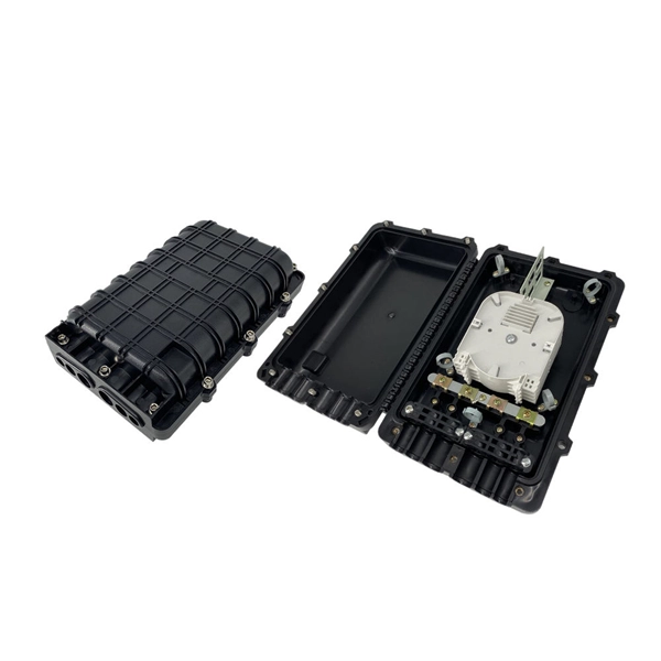
Optical Core Alignment (also called “Profile Alignment”), an optical alignment technique, is used by many models of fusion splicers. The two fibers are illuminated from two directions, 90 degrees apart. Fusion splicing is the process of fusing or welding two fibers together usually by an electric arc. The goal is to fuse the two fibers together in such a way that light passing through the fibers is not scattered or reflected back by the splice, and so that the splice and the region surrounding it are almost as strong as the. Fibre optic splicing trays are an essential part of manipulating and ordering optical fibers inside a network structure. Since the need for higher data rates and effective communication gets more robust, the utilization of optical fibers has become increasingly widespread across multiple spheres of. Corning splice trays use proven designs and fiber organization technology to provide optimum physical protection for fusion and mechanical splicing methods. The trays are engineered for use with indoor or outdoor splice hardware with both loose tube and tight-buffered optical cable designs.
[PDF Version]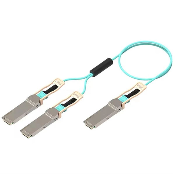
IEC 61537:2023 specifies requirements and tests for cable tray systems and cable ladder systems intended for the support and accommodation of cables and possibly other electrical equipment in electrical and/or communication systems installations. Unless otherwise specified, no part of this publication may be reproduced or utilized in any form or by any means, electronic or mechanical, including photocopying and microfilm, without permission in writing from either IEC or IEC's member National Committee in the country of the requester. It is the first joint effort of NEMA and CSA International to put in one place standards for metal trays per both NEMA and CSA methods. Addresses shipping. 45 2024 by the National Electrical Manufacturers Association. The Core Standards: Overview Key Insight: BS EN 61537 is technically identical to IEC 61537 but includes UK-specific guidance and deviations. Head-to-Head Comparison: Critical.
[PDF Version]Contact us for competitive quotes on any of our power communication and smart grid products
Get a Quote