
The N_Port ID Virtualization (NPIV) is an industry-standard technology that helps you to configure an NPIV capable Fibre Channel adapter with multiple, virtual worldwide port names (WWPNs). The combination of the FCF media access control (MAC) address and the VN_Port MAC. Fibre Channel over Ethernet (FCoE) allows Fibre Channel and Ethernet traffic to be carried on the same physical Ethernet connection between the switch and the servers. The Fibre Channel portion of FCoE is configured as a virtual Fibre Channel interface. Logical Fibre Channel features (such as. A fabric is said to be in Virtual Fabrics mode (VF mode) when the Virtual Fabrics feature is enabled.
Can two switches with fiber ports be directly connected through fiber ports? The answer is yes. The connection between two or more Ethernet switches in a certain way (Uplink port, etc. Moreover, when it comes to bandwidth, no currently available technology is better than single-mode fiber. Here is the list of supported SFP modules for Sx500 series switches: https://www. com/c/en/us/products/collateral/switches/small-business-500-series-stackable-managed-switches/c78-695646_data_sheet. For instance, you can use MGBLX1 or. Other than entry level network switches, most of today's network switches include one or more GiBC (Gigabit Converter) or SFP (Small Form-factor Pluggable) slots. SFP modules insert into these slots and and require two strands of fiber, typically duplex Using multi mode fiber (for runs under 1000. SFP (Small Form-factor Pluggable) is a compact, hot-pluggable network interface module used to connect network devices (switches, routers, firewalls) to fiber optic or copper cables. An SFP interface on networking hardware is a modular slot for a media-specific transceiver, such as for a fiber-optic cable or a copper.
[PDF Version]
Begin by routing each fibre patch cable through the designated cable pathways. Use structured systems like cable trays, ducting, or raceways to prevent clutter and protect fibres from damage. Correct patch-cord installation is essential for maintaining low insertion loss, stable return loss, and long-term reliability in both indoor and outdoor fiber networks. Proper handling, routing, cleaning, bend-radius management, and connector alignment ensure that the optical link meets design. Incorrect routing, contamination, or physical stress on a fiber optic cable can result in attenuation, signal loss, and even complete link failure. According to data from NS Comm's Fiber Performance Lab (2024 Q4 Test Report), poor installation practices can cause up to 2. 5 dB additional signal loss. Proper cable routing, clean connector mating, and adherence to bend radius guidelines aren't optional—they're essential for sustaining long-term network performance and infrastructure lifespan. Ground Outlet: Cables enter inside the rack from the bottom, meaning the patch panel should be mounted in the lower part inside the rack.
[PDF Version]
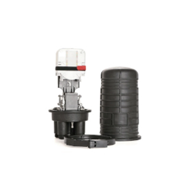
The choice between fusion and mechanical splicing for fiber optic splice module installation depends on project requirements, budget and available infrastructure. Fusion splicing is the process of fusing or welding two fibers together usually by an electric arc. The result is a connection which allows light to pass through without being impeded – we call that a. In this guide, you will find a chronological description of the fusion splicing process, the principal technical standards, and answers to the real-life questions network engineers and procurement teams may have. Let's explore the fundamentals of mechanical and fusion.
In the field, a Fibre Channel switch is a compatible with the (FC) protocol. It allows the creation of a, that is the core component of a (SAN). The fabric is a network of Fibre Channel devices which allows communication, device name lookup,, and. FC switches implement, a mechanism that disable.
When selecting a fiber optic network switch, prioritize models with SFP+ or SFP28 slots for high-speed connectivity, low latency, and support for both single-mode and multi-mode fiber—ideal for data centers or enterprise networks requiring reliable, long-distance transmission 1. Fiber Ethernet switches are crucial for moder n net works. According to a market research report by Technical Market Insights, the fiber optic switch market is projected to grow at a CAGR of. Professional purchasing of high-value photonics products is a substantial responsibility, where a structured decision-making process is essential. They allow for advanced. Choosing the Right Fiber Network Switch, Consider factors like type, number of ports, speed, compatibility, scalability, PoE, and form factor. They are used in a wide range of applications, including telecommunications, data centers, industrial automation, and military and aerospace.
[PDF Version]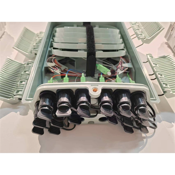
Can two switches with fiber ports be directly connected through fiber ports? The answer is yes. The connection between two or more Ethernet switches in a certain way (Uplink port, etc. This guide focuses on two critical aspects of optical splitters that define FTTH performance: split ratios (how signals are divided) and splitting architectures (how splitters are deployed). By understanding these elements, network operators can design PON (Passive Optical Network) systems that. A cascading connection is a common switch connection method that allows multiple switches to be connected to expand the network size and increase the number of ports. If done incorrectly, it may lead to signal degradation, connectivity issues, or even equipment damage. In this guide, we'll explain how to safely connect a splitter to another splitter, covering both fiber. Cascade distribution means that the optical splitter between the optical line terminal (OLT) and the optical network unit (ONU) is cascaded, and the basic form is "OLT→ optical splitter 1→ optical splitter 2→ONU", where the optical splitter 1 is usually 1:4, and the optical splitter 2 is usually.
[PDF Version]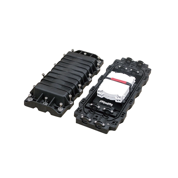
When combined with optical cables like AOC and DAC, these splitters ensure that high-speed internet is delivered seamlessly to every endpoint. They handle large volumes of data distribution with minimal loss. A fiber optic splitter is a passive optical component that divides a single incoming optical signal into two or more outgoing signals, or combines multiple incoming signals into one. This lets you connect more users to one network terminal. Then, smaller pipes split that.
Contact us for competitive quotes on any of our power communication and smart grid products
Get a Quote