
To solder the wires to the relay, tin the end of the required wire, and bend the tinned end of wire in the middle with needle nose pliers to form a "U" shape. Please refer to them during installation in order to avoid problems. The protective measures used will determine suitability for automatic soldering or automatic cleaning. Please follow the recommendations. As electronic devices become more compact, it is becoming a common practice to weld the relay to a PC board (along with the semiconductors) rather than using plug-in relays with sockets. When relays are welded, their functionality may be affected due to seepage of flux into the relay. Where to find. In this guide, I'll walk you through pro-level soldering techniques, safety tips, and insights from real PCB assembly challenges.
The TFT (Thin-Film Transistor) screens used in relay protection applications play a pivotal role in providing operators with clear, actionable information in real-time. Its modular design and powerful DIGSI 5 engineering tool provide tailored solutions. This reference design showcases a two-dimensional (2-D) Qt graphical user interface (GUI), which is typical for. presentation of protection and control relaying. The report will identify methodology behind these practices, present issues raised by the integration of microprocessor relays and the internal logic and external communication configurations, ying. The first numerical relays were released in 1985.
For testing high-voltage microcomputer protection devices, it is recommended to use a microcomputer relay protection tester capable of simultaneously outputting three-phase voltage and three-phase current, and equipped with timing function for digital inputs. Meet all test requirements on site. It can simulate various operating conditions of the power system, such as normal.
Protective relays are commonly referred to by standard device numbers. In the design of electrical power systems, the ANSI Standard Device Numbers denote what features a protective device supports (such as a relay or circuit breaker). These types of devices protect electrical systems and components from damage when an unwanted event occurs, such as an electrical. The protection and control devices in electrical equipment can be referred to by numbers, with appropriate suffix letters when necessary, according to the functions they perform. The device numbers are enumerated in ANSI / IEEE Standard C37.
The article provides an overview of protective relaying principles and their applications for high-voltage power system components. It covers the protection methods for generators, transformers, buses, and transmission lines using various relay types to detect and isolate faults efficiently.
Distance relays, also known as impedance relay, differ in principle from other forms of protection in that their performance is not governed by the magnitude of the current or voltage in the protected circuit but rather on the ratio of these two quantities.OverviewIn, a protective relay is a device designed to trip a when a is detected. The. Electromechanical protective relays operate by either, or. Unlike switching type electromechanical with fixed and usually ill-defined operating voltage thresholds. Electromechanical relays can be classified into several different types as follows: "Armature"-type relays have a pivoted lever supported on a hinge or knife-edge pivot, which carries a moving contact. These relays may.
Guidance on settings for the 132kV system is given in CP338, and for the 33kV and 11/6. Relay protection is essential to ensure the stability, reliability, and safety of electrical power systems. Protective relaying is the backbone of fault detection and system isolation in As transmission systems grow increasingly complex with integration of. This document states the Electricity North West Limited policy for protection for all high voltage systems. It covers standard codes, wiring practices, and norms for protecting generators, transformers, and lines, and provides detailed. Abstract: Covered in this recommended practice is the protection of bus and switchgear used in industrial and commercial power systems. Protection selectivity is partly considered in this report and could be also re-evaluated.

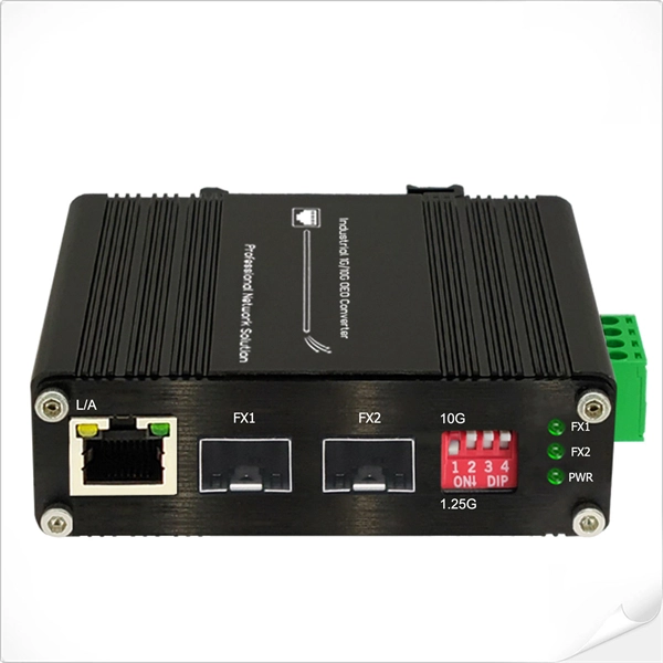
This article explores the current trends, innovations, and market insights surrounding relay protection, focusing on tools like the secondary injection test set, three-phase relay test set, and single-phase relay test set. able sources such as wind and solar. These clean energy sources, connected through inverters and flexible transmission systems, are transforming traditional grids based on synchronous generators into more flexibl cant challenges to system stability. A big difference between conventional electromechanical and static relays is how the relays are wired. Numeric. IEEE/IAS/I&CPSD Protection & Coordination WG Chair Jacobs Canada, Calgary, AB rasheek. com IEEE Southern Alberta Section PES/IAS Joint Chapter Technical Seminar - November 2016 Protective Relays - Technical Seminar Nov 2016 - Copyright: IEEE 2 Abstract: Protective relays and devices. At the core of a modern substation lies the protection relay: an intelligent electronic device (IED) that plays a critical role in maintaining the stability of the power grid by continuously monitoring voltage, current, frequency, and phase angle.
[PDF Version]
A protective relay is an automatic device that detects abnormalities in an electrical circuit and closes its contacts. They are intended to quickly identify a fault and isolate it so the balance of the system. Selectivity is a mandatory requirement for all protection, but the importance of it depends on the application. For example, unselective protection operation during a medium voltage network fault will cause an outage for an unnecessarily large number of consumers. : 4 The first protective relays were electromagnetic. A protective relay is an intelligent electrical device designed to detect faults in power systems and initiate corrective actions such as tripping a circuit breaker.
Contact us for competitive quotes on any of our power communication and smart grid products
Get a Quote