
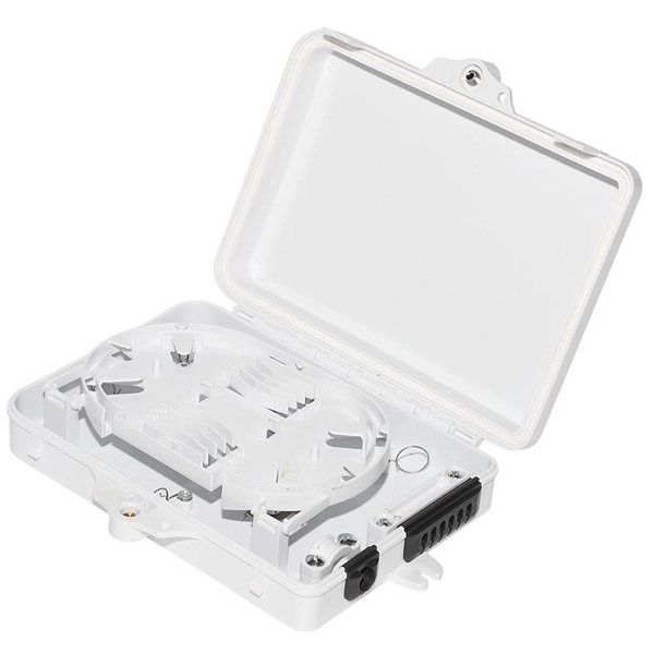
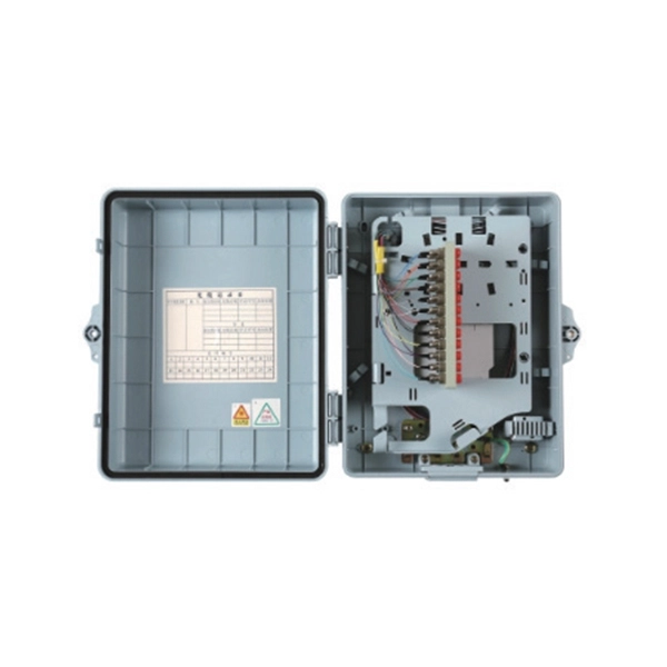
Let's say you have a laser output at 0 dBm (which is 1 milliwatt of optical power). If you use a 1×8 splitter with ~10. 5 dBmCalculate R/T power splitting, Fresnel reflectance, and plate beam displacement. Abridged Optics — Beam Splitter Calculatorv1. See power budget impact instantly, then download a CSV or PDF summary. Common values: 2, 4, 8, 16, 32, 64. Connector loss is always measured as a mated pair. These values are approximate and should not be. Thorlabs' Single Mode 1x8 Fiber Optic Planar Lightwave Circuit (PLC) Splitters allow a user to split a single input signal evenly into eight output signals, which is ideal for passive optical networks (PON) and other high-channel-count applications. In contrast to fused fiber couplers, where light.
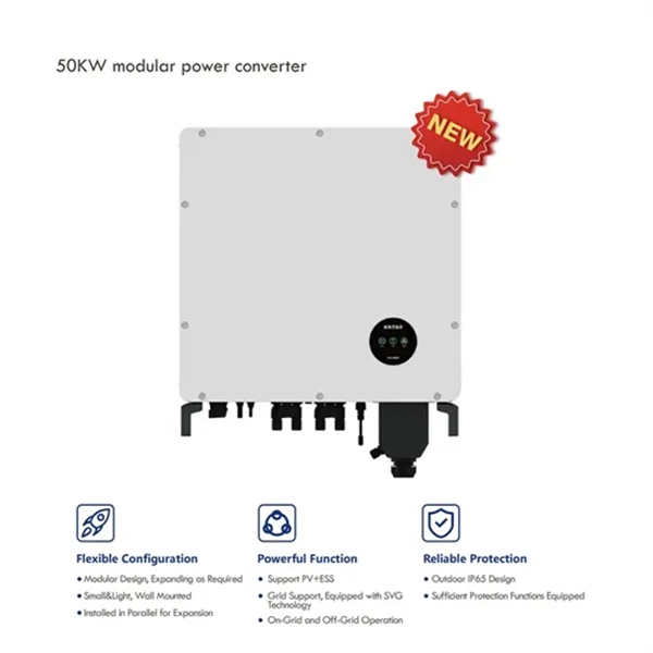
These devices are designed to offer seamless power distribution to multiple systems while enhancing flexibility and reducing downtime. A dual power switching box is precisely the kind of gadget that guarantees a constant flow of electricity as it enables the user to shift the operational state between two different energy supplies. Leading distributors often offer next-day shipping for top stock items, but custom. IP65 vs. IP66 Enclosures for PV Combiner Boxes: Which is Best for Outdoor Solar? Power outage? The generator/backup power supply kicks in automatically, with minimal interruption in equipment operation! 1、Over 100,000 units sold annually: The market votes with its wallet.
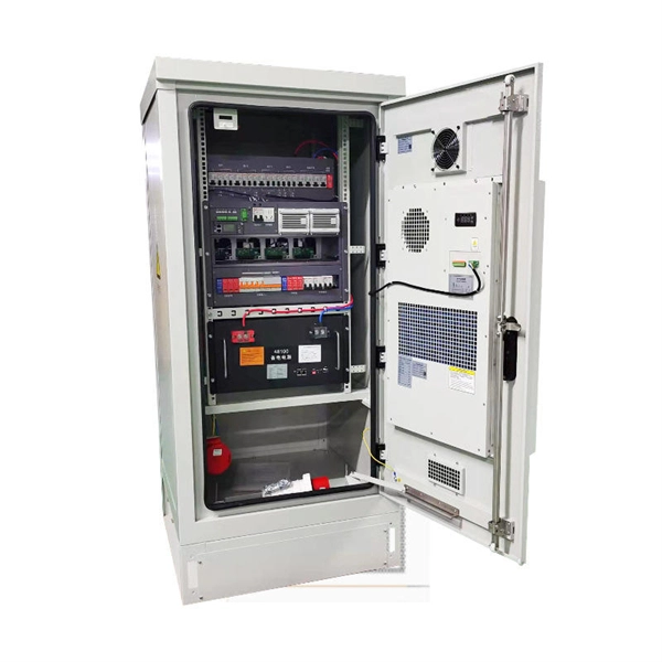
The busbar or vertical grounding strip should be used to provide a visually verifiable, all-copper grounding path. When equipment does not provide a lug-mounting pad, the next best option is to bond the equipment mounting flanges directly to the rack rails. A grounding busbar in a telecom cabinet is a conductive component used to connect all grounding points within the system. A poor layout can quietly undermine reliability and maintenance. In. To mount a bus bar to an assembly structure, hardware (studs, holes, etc. ) can be manufactured into the conductors. Mersen offers in-house conductor plating in tin. Busbar design in switchgear ensures safe, reliable power distribution by balancing current capacity, thermal performance, mechanical strength, insulation, and standards compliance.
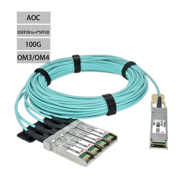
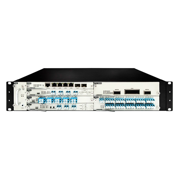
An optical module is a small device that moves data using light. It changes electrical signals into light signals and back again. This helps data travel faster and farther than with copper cables. Optical modules are very important for fast internet, cloud computing . An optical module is a typically hot-pluggable optical transceiver used in high-bandwidth data communications applications. As AI models grow more complex and datasets balloon in size, traditional copper-based interconnects are. Optical modules use light to send data quickly and reliably. They are used in fiber optic communication systems to transmit data over long distances with minimal loss and interference.
Grounding electrode conductor (GEC) – wire connecting the panel to the ground rod. Drive a ground rod into the earth near the panel. Connect the GEC securely to the. This guide will walk you through the process of installing a grounding bar in a Siemens panel, ensuring code compliance and safety. Preparation Safety is paramount. Key steps include driving a ground rod deep into the soil, attaching the grounding wire, connecting it to the panel's grounding. First, panels must have a way to ground all metal components that could be contacted by a person (pretty much all of them). It's the central hub designed to safely channel dangerous fault currents away from your equipment and, more importantly, away from your personnel. You'll learn what tools you need, how to do the job safely, and how to check if everything is working properly.
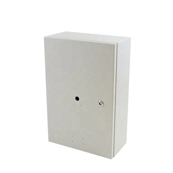
Primary distribution box: three-phase power supply, ground wire and zero wire are introduced from the transformer. 4kV), power distribution is achieved through three levels of distribution boxes: the main distribution board, secondary distribution boards, and tertiary distribution boards. Main Distribution Board Serves as the primary. Power distribution hierarchy in building. Let's make an example for clarity: A newly constructed residential area introduces a 10kV power line to a substation. From the transformer's low-voltage side (0. Features bottom entry and exit cables, front-opening doors, copper busbars for main connections, metering systems, and rainproof tops for outdoor work.
Optical power meters can measure the power of both single-mode and multimode fibers. In single-mode fiber, the rays travel down its entire length without any internal reflection at all. Other general purpose light power measuring devices are usually called radiometers, photometers, laser power. Yes, it provides precise optical power measurements in dBm, but it does not support light decay testingthis claim in product listings is misleading and false. Can I trust the APM80C to accurately measure optical power in my daily fiber optic maintenance tasks? 2. How does the APM80C compare to. In this video, we explain how to repair an Optical Power Meter that powers ON but does NOT show any optical power reading. You will learn: • How an Optical Power Meter. Since optical fiber power meters (OFPMs) are a very common type of optical test equipment, NIST has developed and implemented measurement services to help characterize these instruments. The offering ranges from a low cost, hand-held meter to the most advanced dual channel benchtop power meter available in the market.
[PDF Version]Contact us for competitive quotes on any of our power communication and smart grid products
Get a Quote