
In this blog post, we'll take a deep dive into the key performance tests for fiber optic patch cords — polarity verification, insertion loss and return loss measurement, 3D interferometric endface metrology, and endface inspection — along with the relevant standards . In this blog post, we'll take a deep dive into the key performance tests for fiber optic patch cords — polarity verification, insertion loss and return loss measurement, 3D interferometric endface metrology, and endface inspection — along with the relevant standards . One of the key performance indicators of a fibre optic patch cord is its insertion loss. Insertion loss refers to the reduction in power density (signal) that occurs when a signal is transmitted through the patch cord. This article explains their concepts, standards, testing methods, and FiberMania's quality assurance workflow to ensure optimal network performance. Fiber optic patch cords are crucial components in. Insertion Loss (IL) is one of the most fundamental performance indicators in fiber optic networks.
[PDF Version]
Fusion couplers, made by melting a section of twisted fibers, offer the lowest insertion loss (~0. 3 dB) and highest power handling, with a limited wavelength bandwidth of ±40 nm and polarization extinction ratio below 23 dB. Optical splitters, encompassing FBT (Fused Biconical Taper) couplers and PLC (Planar Lightwave Circuit) splitters, are prevalent passive optical devices designed to divide fiber optic light into multiple segments based on a specified ratio. T PON standards such as GPON, XGS-PON and new 25 and 50G standards. We offer a full line of fiber optic couplers and splitters supporting SM, MM, PM, large core, and double-clad fibers across 300–2000 nm, with power handling up to 100 W and operating temperatures up to 300°C. Three fabrication methods are employed: fusion, micro-optics, and planar lightwave circuit. Carrier-grade standard insert type 1-4 optical splitter, low insertion loss, uniform light splitting 2. Uniform light splitting and stable transmission using high-quality transmission.
[PDF Version]
RL (dB) is the ratio of the reflected optical power to the incident optical power at the input port of optical signals. These are known as passive optical splitters, and they perform the function. Optical splitters, encompassing FBT (Fused Biconical Taper) couplers and PLC (Planar Lightwave Circuit) splitters, are prevalent passive optical devices designed to divide fiber optic light into multiple segments based on a specified ratio. Understanding the types of splitters, their impact on network performance, and how to measure their losses ensures high-quality network operation and facilitates optimal splitter selection based on. Return loss (RL) is also called reflection loss. RL (dB) is the ratio of the reflected. By dividing a single optical signal from a central Optical Line Terminal (OLT) into multiple outputs for Optical Network Terminals (ONTs) at users' homes, splitters eliminate the need for dedicated fibers to each residence—slashing infrastructure costs while scaling network reach.
[PDF Version]
Return Loss (RL): ≥ 60 dB (APC), ≥ 50 dB (UPC). Ferrule Geometry: Must pass 3D interferometer inspection (radius, apex offset, fiber height). Among them, SC/APC Fiber Optic Patch Cords feature excellent return loss performance and high system stability, making them indispensable in optical transmission scenarios sensitive to reflected light, such as cable television networks (CATV) and passive optical networks (PON). SC (Standard. Professional Guide: This particular product is a SC to SC Fiber Patch Cord with specifications, application uses, and testing procedures. The reliability and efficiency of an optical network heavily depend on the quality of these patch. cked in one clear plastic bag. Test data sh uld be attached with each bag. Other shipping. We offer full-service OEM and ODM solutions for fiber optic cables, assemblies, and connectivity products — from design and prototyping to global production and logistics. Multimode SC-SC Duplex Patch Cab. It is dismountable, flexible and featured wit small size, low insertion loss and lower price.
[PDF Version]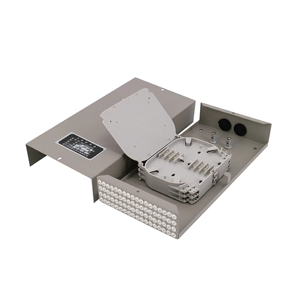
Reflectance (which has also been called "back reflection" or optical return loss) of a connection is the amount of light that is reflected back up the fiber toward the source by light reflections off the interface of the polished end surface of the mated connectors and air. It is also called. High connector loss (e., insertion loss), low return loss, or high reflectance will impair an application (i. 10GBASE-LRM) from running on a network. A high return loss is a good thing and usually results in low insertion loss. It is expressed in decibels (dB) and represents the forward power loss due to attenuation and connection inefficiencies.
A uni-directional test will be conducted on all pigtail splices with no greater than a. 8 dB after 5 repeated attempts results in the replacement and re-splicing of that pigtail. dB loss in fiber optics is the reduction in light signal strength as it travels through a fiber cable, measured in decibels. The connector end is polished and tested under factory conditions, ensuring low insertion loss and high return loss. 1 dB per 100 feet (30 m) for 850 nm, 0. For singlemode fiber, the loss is about 0. While some loss is expected, excessive or unexpected loss can lead to poor performance, network downtime, and signal failure. Recognizing what constitutes too much loss is essential. At TREND Networks, we are frequently asked how much loss is allowed when conducting testing on fibre optic cabling.
Contact us for competitive quotes on any of our power communication and smart grid products
Get a Quote