
If the optical module is faulty, replace it. If the fault is caused by incorrect configuration or networking environment, change the configuration or networking environment. The working rate, duplex mode, and. Based on typical issues encountered with optical modules in daily switch applications, this document summarizes basic troubleshooting steps for resolving common faults: 1. Common Anomalies and Solutions (Quick. Customers in the use of optical modules will more or less encounter a variety of failure problems, such as optical module model selection is correct, the use of jumper is correct and some common problems, customers have the ability to judge and have a clear solution, but for some of the use of. An optical module is a critical component in modern optical communication systems, directly affecting transmission stability, network reliability, and operational efficiency. However, during installation and daily operation, various issues may arise.
[PDF Version]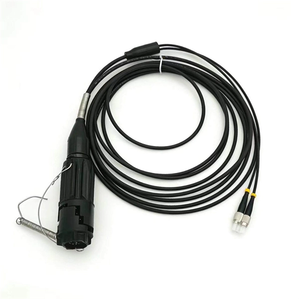
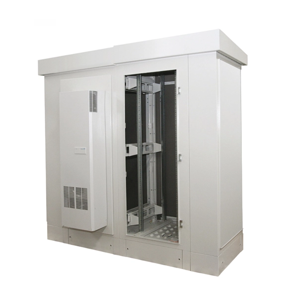
This transparent protective cover is designed for panels and control cabinets, providing maximum protection in demanding industrial and environmental conditions. (2) Flexible options including plastic waterproof distribution box and DIN rail waterproof electrical distribution box for versatile wiring needs. - The folding structure and automatic buffer closure make it easy to open and close the power supply cover of this switch box. Outdoor Waterproof Enclosure Box originally developed for modern industrial and residential applications, the TSM series. These covers are designed for a limited number of circuit breakers in residential or small commercial settings where electrical loads are lower and where only one phase of electricity is needed.
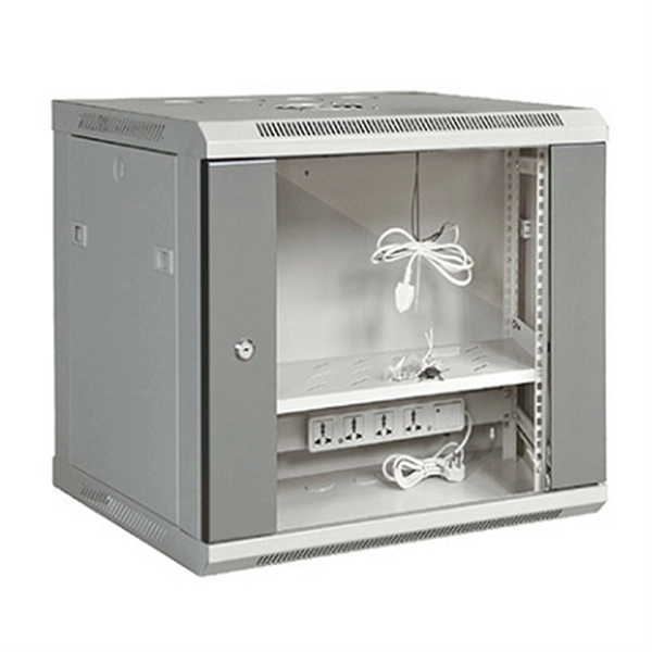
Industrial ethernet switches operate from -40°C to +75°C, resist vibration and EMI, and use DIN-rail mounting — features office switches simply do not have. PoE and fiber. With the increased use of Ethernet-based systems, more Ethernet switches are being used to create the necessary controls topology. The aplSwitch Field can be installed in Zone 2 and integrates smoothly into existing. Antaira Technologies breaks down 10 mission-critical capabilities that separate industrial-grade switches from commercial-grade compromises — and why it matters on the plant floor. LAS VEGAS, NV, May 12, 2026 – When a network failure means halted production or compromised safety, "good enough".
DOM (Digital Optical Monitoring) is an integrated real-time monitoring solution embedded in SFP optical modules. It collects, transmits, and analyzes operational parameters, providing administrators with actionable insights into link performance. SFP (Small Form-factor Pluggable) is a compact, hot-pluggable network interface module used to connect network devices (switches, routers, firewalls) to fiber optic or copper cables. Optical link diagnostics are central to network maintenance, and DOM technology enables. Digital Optical Monitoring (DOM) technology, a key feature of SFP optical modules, provides real-time, comprehensive parameter support for optical link diagnostics, making it indispensable for troubleshooting. The user's attention is called to the possibility that implementation of this specification may require the use of. This document defines an enhanced Digital Diagnostic Monitoring Interface (DDMI) available in Finisar SFP and SFP+ optical transceivers. (Note: the DDMI also applies to legacy GBIC optical transceivers.
[PDF Version]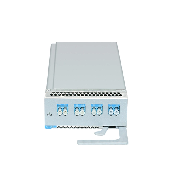
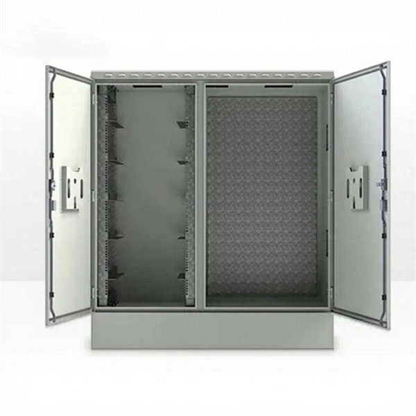
Strain relief bar (SRB) is a cable management solution, which in most cases, attaches to the back of the rails via the strain relief bar brackets. It also helps you arrange interface cables in such a way that the power modules, fan assembly, and air filte n for the Cisco 10005 router. The cable management bracket enables you to route the cables outside the router and away from the Routing Engines and LMICs. Figure. These rack types are broken down in Table 2 into 4-post and 2-post styles. 4-post rack types contain vertical mounting flanges with either square-hole, unthreaded round-hole, or threaded round-hole designs as part of the rack and rail interface. This washer is not installed. The following guidelines provide cabling information for installing, migrating, relocating, or upgrading your system: Position drawers in racks to allow enough space, where possible, for cable routing on the bottom and top of the rack, and between drawers. Shorter drawers must not be placed between.
[PDF Version]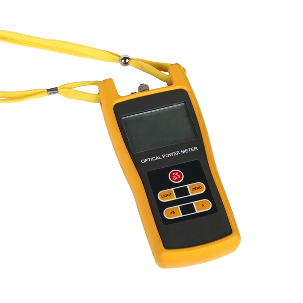
In digital transmission, the number of bit errors is the number of received bits of a data stream over a communication channel that have been altered due to noise, interference, distortion or bit synchronization errors. The bit error rate (BER) is the number of bit errors per unit time. The bit error ratio (also BER) is the number of bit errors divided by the total number of transferred bits during a studied tim. ExampleAs an example, assume this transmitted bit sequence: 1 1 0 0 0 1 0 1 1 and the following. The packet error ratio (PER) is the number of incorrectly received divided by the total number of received packets. A packet is declared incorrect if at least one bit is erroneous. The expectation value of the PER is. In a communication system, the receiver side BER may be affected by transmission channel,,, problems,, wireless , etc. The BER m.
The troubleshooting process typically involves three main steps: fault detection, fault analysis, and fault resolution. For example, unselective protection operation during a medium voltage network fault will cause an outage for an unnecessarily large number of consumers. Megger's smart relay testing solutions and expert support help you validate protection performance, improve system reliability, and ensure continuity of power across your network. The issue will be recorded in an internal memory.
Contact us for competitive quotes on any of our power communication and smart grid products
Get a Quote