

In electric power distribution, a busbar (also bus bar) is a metallic strip or bar, typically housed inside switchgear, panel boards, and busway enclosures for local high current power distribution, transmission, or switching substations. They are also used to connect high voltage equipment at electrical switchyards, and low-voltage equipment in battery banks. They are generally uninsulated, and h. Design and placementThe busbar's material composition and cross-sectional size determine the maximum current it can safely carry. Busbars can have a cross-sectional area of as little as 10 square millimetres (0.016 sq in), but. • – Data transfer channel connecting parts of a computer• – Low resistance electrical conductor for high current transmission and distribution• – Modular approach t. • Elmore, Walter A. (1994). Protective Relaying Theory and Applications. Marcel Dekker.• Paschal, John (2000-10-01). Electrical Construction & Maintenanc.
[PDF Version]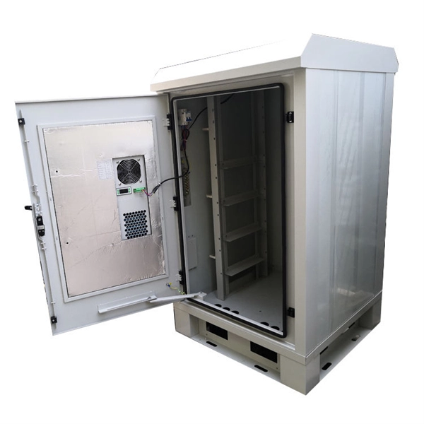
To support the above-mentioned total cell tower build costs, Dgtl Infra references examples from some of the largest independent cell tower companies in the world, including American Tower, Crown Castle,.
The base station can be divided into two modules: the RRU for transmitting signals and the BBU for processing signals. Generally, the. RRU and BBU are crucial components in base station construction, enabling a distributed architecture that improves efficiency and reliability. The distributed site separates the base station BBU and RRU.
This explosion-proof distribution box is built for reliable protection in demanding industrial settings. Flameproof enclosure Ex d IIB+H2 Copper-free aluminium enclosure, powder coated surface. Equipped with a specialized hinge structure which can prevent damage to the flameproof joints when opening and closing the box and greatly prolongs the service life. The boxes can be combined and installed. Terminal boxes and junction boxes from Pepperl+Fuchs are designed to protect signal and power distribution networks in explosion-hazardous and challenging environments. With a wide range of enclosure materials, sizes, ambient temperature ranges, and customizable configuration s, these solutions can. Atexdelvalle offers world-class explosion-protected solutions guaranteeing highest quality and performance with no compromise. Downtime can also disrupt daily operations. Branch circuit:Maximum current is 100A.
[PDF Version]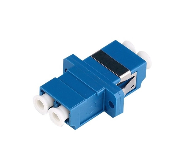
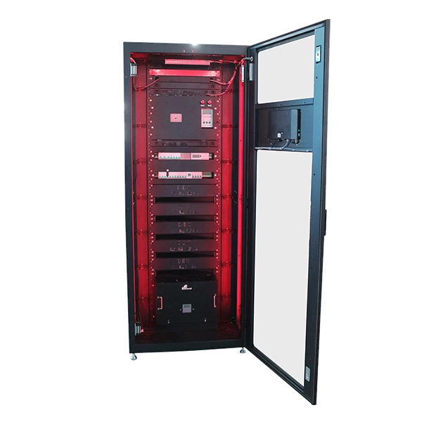
A practical guide to how protective relays detect faults, trip circuit breakers, coordinate protection zones, and improve power system reliability. Core idea: Protective relays monitor electrical quantities and command protective devices to isolate faults or abnormal operating. A protective relay is an intelligent electrical device designed to detect faults in power systems and initiate corrective actions such as tripping a circuit breaker. Its main purpose is to safeguard electrical equipment like transformers, generators, and transmission lines from damage due to. IEEE/IAS/I&CPSD Protection & Coordination WG Chair Jacobs Canada, Calgary, AB rasheek. Recognized under 2(f) and 12 (B) of UGC ACT 1956 (Affiliated to JNTUH, Hyderabad, Approved by AICTE - Accredited by NBA & NAAC – 'A' Grade - ISO 9001:2015 Certified) Maisammaguda, Dhulapally (Post Via. Circuit Breakers: These devices are crucial for automatically disconnecting the.
[PDF Version]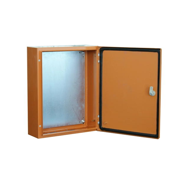
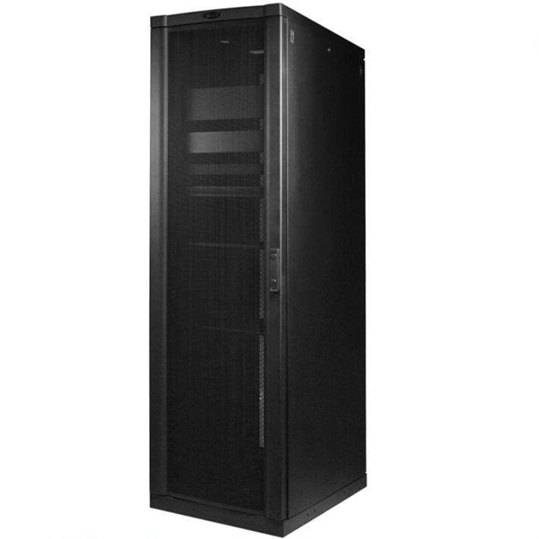
Step1 : Identify the optical cabinet and network operating center, and find the fiber optic splitter. Step 5: Patching from the splitter port to the user. Proper installation and regular maintenance of fiber optic patch cords play a crucial role in achieving optimized network performance, preventing signal errors, and extending service life. Fiber Optic Patch Panel Explaination Fiber optic patch panels are mostly mounted in 19 inch relay racks, but also on freestanding rails, cabinets. Correct patch-cord installation is essential for maintaining low insertion loss, stable return loss, and long-term reliability in both indoor and outdoor fiber networks. Whether you're connecting a data center, a corporate network, or a high-density fiber infrastructure, correct installation methods are essential.
Contact us for competitive quotes on any of our power communication and smart grid products
Get a Quote