

This guide covers the critical steps, from selecting the right electrical cable tray and performing accurate cable fill calculations to managing a safe cable pull through and ensuring all bonding and grounding requirements are met. But before you lay the first tray or clamp down a single cable, you need a solid plan. This guide breaks down the process step by step. Need to renew your Electrician license? Pick your state and browse state-approved Electrician CE courses — complete your continuing education hours online, with instant reporting. Article Summary: A compliant cable tray installation requires a thorough understanding of NEC Article 392, proper. Here is a step-by-step guide on how to install a standard metal cable tray system (e. The Cable Tray ng standards, performance standards, test standards and application in this document have been tested extens ompetent professional en completely installed, without damage either to conductors or. Bilal Switchgear Engineering knows that a messy electrical room is a dangerous one.
[PDF Version]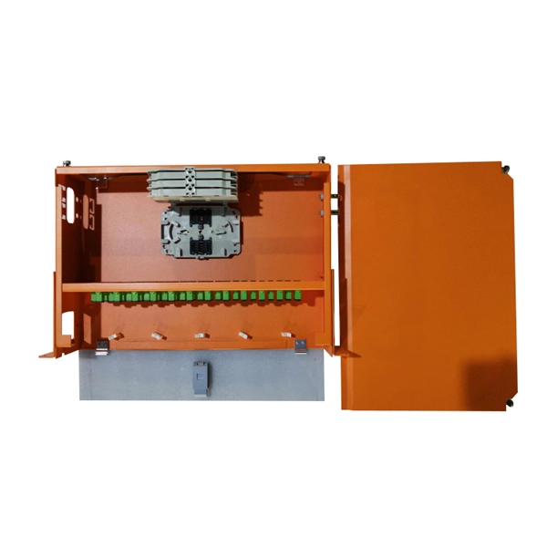
In order to start configuring a switch, you usually use the configure terminal command from privileged EXEC mode to enter global configuration mode. You can make adjustments in this mode that impact the router or switch as a whole. The Cisco IOS user interface is divided into many different modes. The commands available to you depend on which mode you are currently in.
Once you have a BGA breakout that does not kill your signal integrity, you will have no problem bringing channels out to the optical modules. Simply design to the required differential impedance, minimize tur.
This guide covers split load vs dual RCD vs RCBO board configurations, circuit arrangement and allocation, BS 7671 labelling requirements, type testing under BS EN 61439, SPD installation, wiring best practice, and the common mistakes found during EICR inspections. MCBs (Miniature Circuit Breakers) protect individual circuits from overcurrent and short circuits. Choosing the right MCB requires considering rated current. Power Distribution Equipment is a term generally used to describe any apparatus used for the generation, transmission, distribution, or control of electrical energy. This section concentrates upon commonly used power distribution equipment: Panelboards, Switchboards, Low-Voltage Motor Control. Done right, it ensures safety, compliance, and long-lasting performance. In this guide, we'll break down everything you need to know to install a distribution box correctly and confidently.
[PDF Version]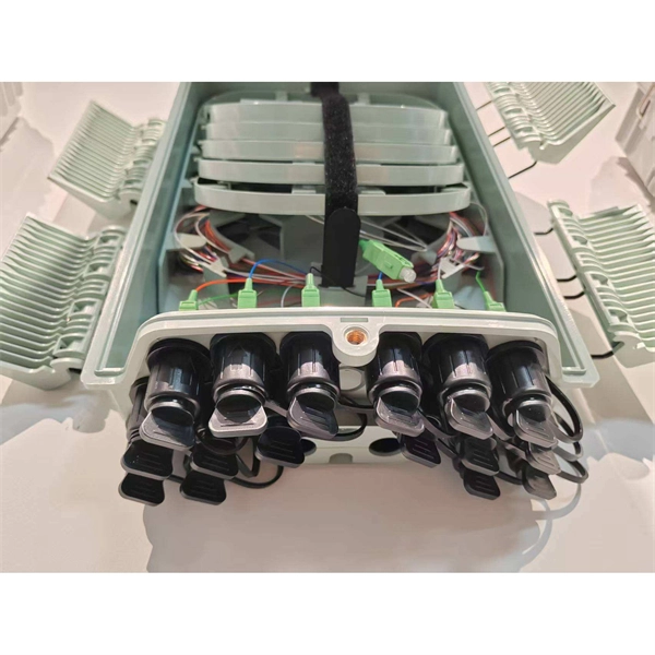
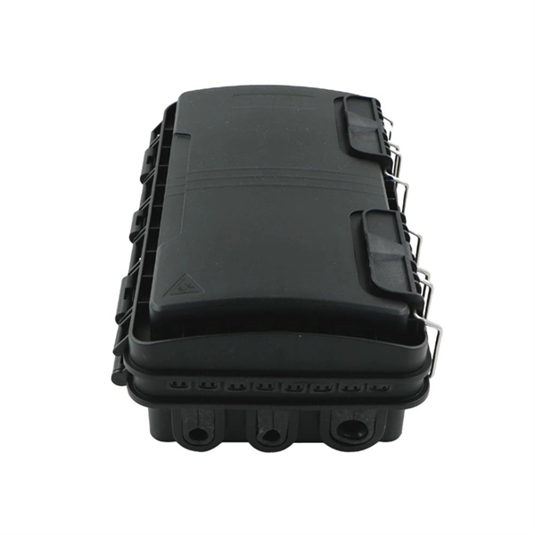
Can two switches with fiber ports be directly connected through fiber ports? The answer is yes. The connection between two or more Ethernet switches in a certain way (Uplink port, etc. This guide focuses on two critical aspects of optical splitters that define FTTH performance: split ratios (how signals are divided) and splitting architectures (how splitters are deployed). By understanding these elements, network operators can design PON (Passive Optical Network) systems that. A cascading connection is a common switch connection method that allows multiple switches to be connected to expand the network size and increase the number of ports. If done incorrectly, it may lead to signal degradation, connectivity issues, or even equipment damage. In this guide, we'll explain how to safely connect a splitter to another splitter, covering both fiber. Cascade distribution means that the optical splitter between the optical line terminal (OLT) and the optical network unit (ONU) is cascaded, and the basic form is "OLT→ optical splitter 1→ optical splitter 2→ONU", where the optical splitter 1 is usually 1:4, and the optical splitter 2 is usually.
[PDF Version]Contact us for competitive quotes on any of our power communication and smart grid products
Get a Quote