
Passive optical networking (PON), like active optical networking, uses fiber-optic cabling to provide Ethernet connectivity from a main data source to endpoints. In practice, PONs are typically used for the last mile between Internet service providers (ISP) and their customers. It uses only optical fibers to transmit data, voice, and video services. A PON network consists exclusively of passive optical components. "Passive" refers to the use of optical fiber cables connected to an unpowered splitter, which in turn transmits data from a service. In a PON access network there are two end-points with active (powered) electronic transmission equipment, connected by passive (non-powered) equipment known as outside fiber plant.
The SFP port is a built-in optical port of a Gigabit Ethernet switch, so it cannot be directly connected with a twisted pair or a jumper. It needs to be connected to an optical module first, and then it can be transmitted with an optical fiber patch cord. This project. This installation note provides the technical specifications and installation instructions for the Gigabit Ethernet Converters (GBICs) that you install in Catalyst 4000 or Catalyst 5000 series Gigabit Ethernet ports that accept GBICs. It uses a double-layer board design + minimal peripheral components to save costs to the maximum extent. In previous lesson, we had discussed about Ethernet (10 Mbps) and FastEthernet (100 Mbps) Straight-through and Cross-over. Ethernet is a family of specifications that governs a few different things: It covers all the different wiring specifications (10BASE-T, 100BASE-TX, 1000BASE-T, etc. ).
[PDF Version]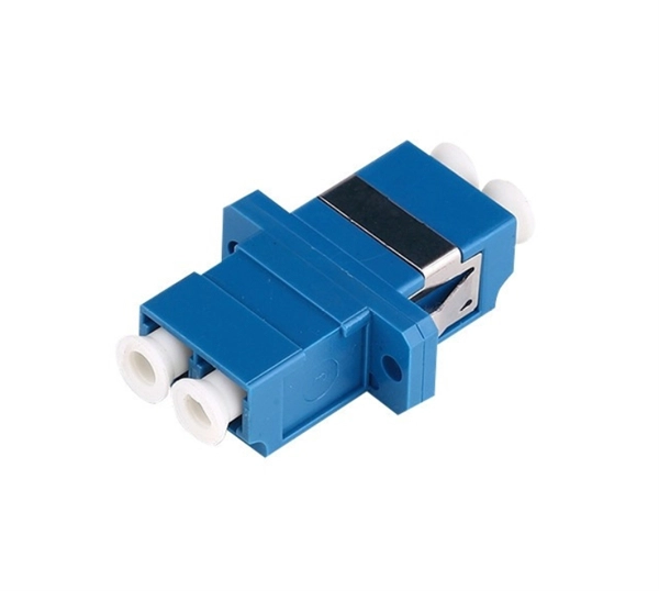
The bends, tees, crosses, risers and reducers of wire mesh cable tray can be easily and quickly made live at the project by using a bolt cutter. Since the jaws of the bolt cutter drags a layer of zinc across the cut end and forms a protective layer. Only two splices are required to securely connect tray widths of wire basket tray. Engineers and contractors in North America and around the world have found. How to cut Oglaend System Support Channels, Cable Ladders and Cable Trays.
When multiple cables enter an electrical box, “pigtailing” is the preferred connection method. Pigtailing involves twisting the incoming hot, outgoing hot, and a short segment of matching wire (the pigtail) together with a wire nut. In this guide, we'll break down everything you need to know to install a distribution box correctly and confidently. Choose the right box based on environment (indoor/outdoor), load capacity, and durability. Check for proper IP/NEMA ratings and material quality. Wiring Direction: Wiring between the main circuit breaker and each branch circuit breaker in the box generally. This guide covers split load vs dual RCD vs RCBO board configurations, circuit arrangement and allocation, BS 7671 labelling requirements, type testing under BS EN 61439, SPD installation, wiring best practice, and the common mistakes found during EICR inspections. A high-reliability LV panel does more.
[PDF Version]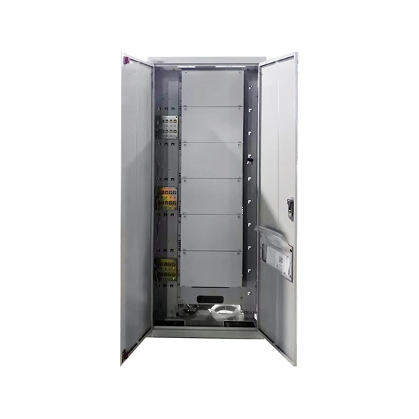
This step-by-step guide shows reliable ways to mount plastic conduit and organize wiring in a home workshop. 📌 If you plan to use these methods later — save the video. ⏱️ Timestamps: 0:00 – Corrugated pipe fixing method (secure mount) 0:55 – Cable management with zip ties 1:23 –. Fiber optic cable is sensitive to excessive pulling, bending, and crush forces. Any such damage may alter the cable's characteristics to the extent that the cable section may have to be replaced. Repairs focus on restoring the light path with minimal signal loss (<0. The cable should be bent as little as possible. Safe Handling The broken. Fiber optic cables are critical components of modern communication networks, transmitting vast amounts of data at lightning speeds.
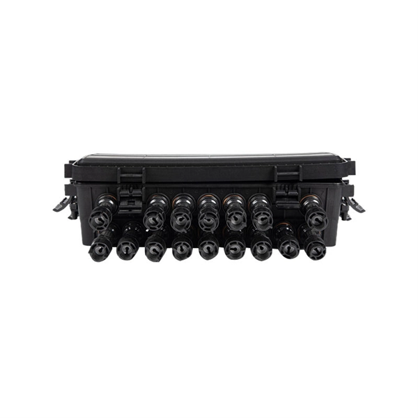
Fusion splicing uses a precision arc discharge between two electrode rods to heat and fuse the cleaved fiber ends together. When done correctly, the splice point becomes essentially seamless—the glass of the two fibers melts together into a single, continuous strand. Executive Summary: A fiber optic pigtail is one of the most commonly specified yet least understood components in structured cabling. Get the wrong connector type, the wrong polish, or skip proper fusion splicing technique—and you're looking at elevated signal loss, increased back reflection, and a. Fusion splicing is the backbone of modern fiber optic installations—and it's the primary method used when working with fiber optic pigtails. This. Fiber optic fusion splicing is on the rise and Corning's Pigtailed Splice Cassettes enable faster field splicing and easy modular management of connectorization within the housing. This design makes pigtails the ideal choice for applications where fibers from a large cable must be terminated at an ODF (Optical Distribution Frame), terminal box, or patch panel.
[PDF Version]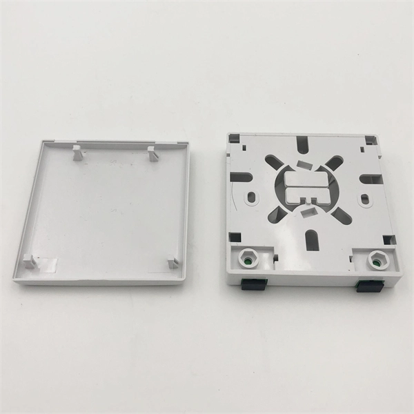
The 2025 standards, set by The Fiber Optic Association, Inc., require you to follow strict rules for both phases. During installation, you should never bend a fiber optic cable tighter than 20 times its diameter. Installers must understand these specifications and know how to install cables without. The correct bend radius calculation is a fundamental prerequisite for high-quality fiber optic installations and is decisive for long-term network performance and reliability. Because of this, exceeding the operating temperature of the acrylate coating can also cause microbending in fiber cabling, which can also result in significant attenuation. Macrobending occurs when the fiber optic cable is bent on a larger. The fiber optic bend radius refers to the smallest radius a fiber cable can be bent without causing unacceptable signal degradation or physical damage. Proper bend radius control ensures the integrity of optical performance and protects the glass. Fiber optic cables have revolutionized communication networks, providing extremely fast data transmission through pulses of light traveling along thin glass fibers. So an important question arises:.
[PDF Version]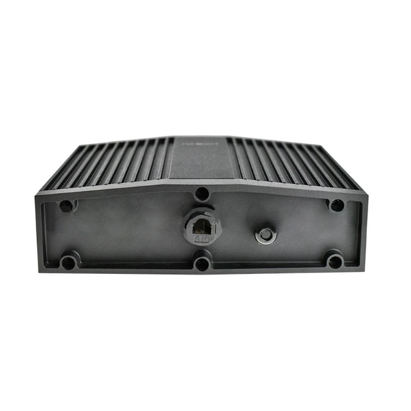
To solder the wires to the relay, tin the end of the required wire, and bend the tinned end of wire in the middle with needle nose pliers to form a "U" shape. Please refer to them during installation in order to avoid problems. The protective measures used will determine suitability for automatic soldering or automatic cleaning. Please follow the recommendations. As electronic devices become more compact, it is becoming a common practice to weld the relay to a PC board (along with the semiconductors) rather than using plug-in relays with sockets. When relays are welded, their functionality may be affected due to seepage of flux into the relay. Where to find. In this guide, I'll walk you through pro-level soldering techniques, safety tips, and insights from real PCB assembly challenges.
With an angle grinder and the right cutting disc specially designed for the material, almost any type of steel or non-ferrous metal can be worked with without any problems. A chamfer is also often used to make a later stage in assembly easier – specifically the joining of two. The edge grinding machines from the KSM series for straight edges are designed for the precise chamfering and deburring on hard materials. The. Chamfer Mills or Chamfer Tools are an essential part of any CNC'ers tooling. What is a. A chamfer is defined as an angled face applied to a workpiece edge and the angle chosen is typically either 45° or 30°. It removes sharp corners and adds a clean, finished look. This precision process, pioneered by innovators like Charles Cotta in transmission manufacturing, transforms dangerous, jagged surfaces into smooth, angled transitions that improve safety and. CNC Chamfering can be used to create various edge profiles such as V-shape, U-shape, and square-shape. In this process, the actual cut depends on the setup and the type of tools to be employed. Here you will find out what is a chamfer, and important facts that machinists must know about chamfer.
[PDF Version]
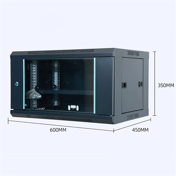
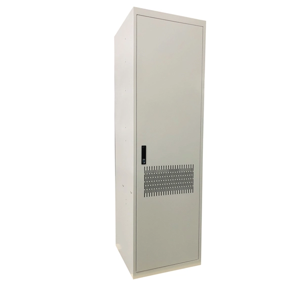
In network cabling, outdoor connections generally use fiber optic cables. When these optical fibers are installed or laid out, a Fiber Termination Box, or FTB, is used to distribute and protect the optical fiber link.
Contact us for competitive quotes on any of our power communication and smart grid products
Get a Quote