
For optical fiber cables, each individual fiber is color-coded in a specific sequence to facilitate easy identification. The standard color sequence is based on a 12-fiber system, which repeats for cables with higher fiber counts. The TIA/EIA-598-C standard is the most widely followed guideline for color coding in optical fiber cables, both for loose-tube and. They each contain a central transparent core, usually circular in cross-section, surrounded by an annular cladding. The core can transmit light for long distances with low loss because of total internal reflection at the interface between. Prysmian uses the US industry standard repeating 12-color sequence. Tubes with binder threads: A blue and orange thread binder is used to separate two groups of fibers. The blue unit has the first 12 fibers and. Fiber Optics is the communications medium that works by sending optical signals down hair-thin strands of extremely pure glass or plastic fiber.
[PDF Version]
Scientists at the University of Southampton have developed a radical new hollow-core optical fiber that carries light through air instead of solid glass. The result? Data that moves faster, farther, and with a thousand times more transmission power than today's networks can handle. Hollow-core optical fibers (HCFs) have unique properties like low latency, negligible optical nonlinearity, wide low-loss spectrum, up to 2100 nm, the ability to carry high power, and potentially lower loss then solid-core single-mode fibers (SMFs). However, glass imposes a fundamental physical limitation because light travels through it approximately 30 percent slower than through air. Recent advances in reducing optical losses and the prospects for telecommunication applications of hollow-core fibers, issues of transporting high-intensity optical radiation, and results on nonlinear compression and the generation of ultrashort pulses in gas-filled hollow-core fibers are reviewed. This isn't just. In addition to beating conventional telecom fiber on loss and latency, hollow-core fibers are enabling new approaches to applications like sensing, fiber lasers and optical tweezers.
[PDF Version]
The fabric burn test — also called fiber burn testing or pyrolytic analysis — is a qualitative identification method in which a small sample of fabric or yarn is exposed to an open flame. By observing how the material behaves near, in, and after the flame — including the flame color, rate of. The Textile Wiki pages are a publication of the Textile Specialty Group of the American Institute for Conservation of Historic and Artistic Works. Publication does not endorse or recommend any treatments, methods. Burn test is one of the simple and commonly used methods for fiber analysis. By analyzing factors like flame speed, smoke color, odor, and residue, you can determine what a fabric is made of. Also, useful for the sourcing team, who continuously trying to verify fiber composition from dead stock suppliers.

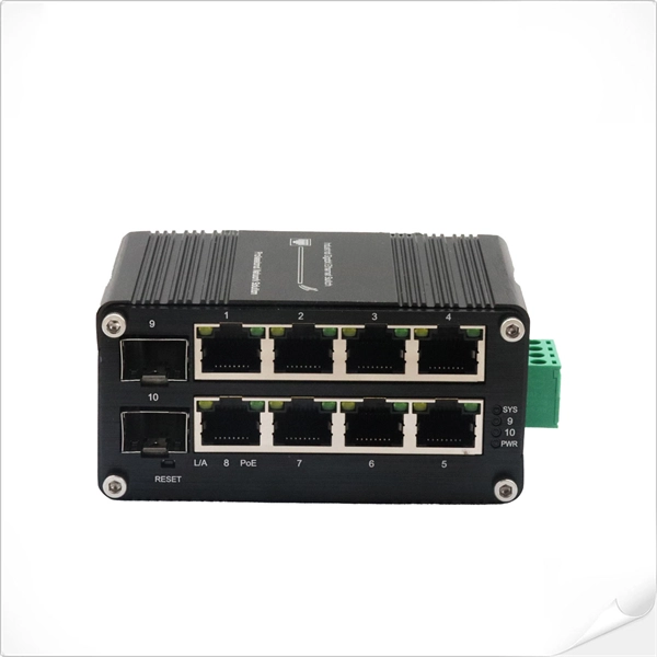
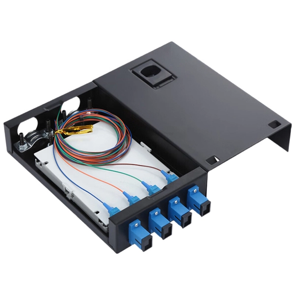
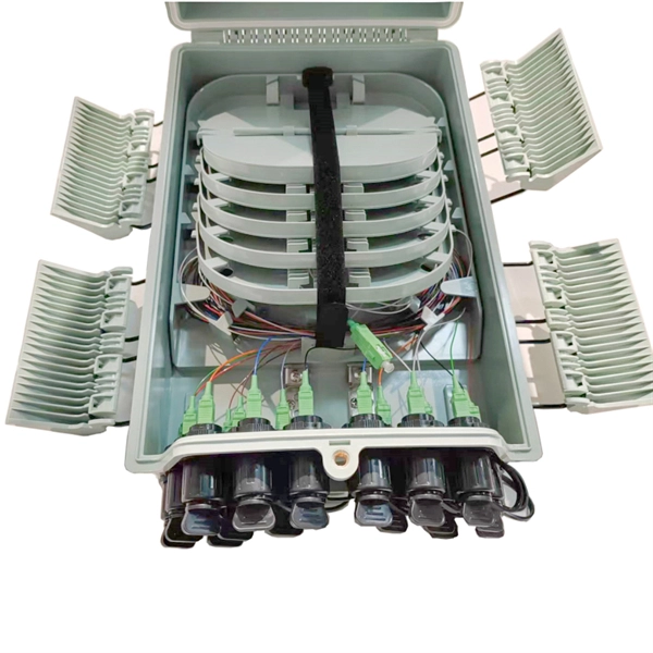
The ideal structure for connecting two fiber cables is as follows: Cable A → Adapter Panel → Patch Cord → Adapter Panel → Cable B How It Works Fiber Adapters: Bridge the two connector types (e., SC to LC, or SC to SC). Patch Cords: Provide a short, flexible link between adapters. To connect two optical fibers together, a process called splicing is used. This involves aligning the two fiber ends and then fusing them together using heat or a specialized tool. Fiber cabinets, patch panels, and distribution frames are designed to manage and protect terminations, not for direct splicing. Data Servers are at Location A.
We develop averaged equations to model nonlinear propagation in multimode fibers that are valid in all regimes of random, linear, intermodal coupling. A fundamental question that has been raised in this context is whether it is legitimate to compute these coefficients from the overlap integrals. We analyze the spatiotemporal solitary waves of a graded-index multimode optical fiber with a parabolic transverse index profile.
This paper describes a newly developed butt joint type hollow-core fiber connector with protected fiber ends. It can typically realize nearly 0.5-dB insertion and 45-dB return loss without physical contact. I.
A fiber-optic cable, also known as an optical-fiber cable, is an assembly similar to an but containing one or more that are used to carry light. The optical fiber elements are typically individually coated with plastic layers and contained in a protective tube suitable for the environment where the cable is used. Different types of cable are used for in different applications, for exa.
Start adjusting the fiber coupler by turning the three positioning screws one after the other up to half a turn in each direction, until the power meter detects a signal. How measured fiber parameters help to choose the best coupling and collimation optics. A stable measurement setup is fundamental for any successful measurement. A major cause of frustration and error is the need to continuously readjust optomechanical equipment because of continuous instabilities. This tab provides a brief explanation of how we determine several key specifications for our 1x2 couplers. Polarization-maintaining single- mode fibers (PM fibers) are rotation-ally non-symmetric. When using fiber optics, one often needs to use fiber couplers for various purposes. Directional 2 × 2 couplers (see Figure 1) are usually used for. The T F D is a compact, rugged fiber coupler designed to be easy to use, while still having all OPTICA IBER OCK the required degrees of freedom to allow maximum coupling efficiency to be achieved. These specialized devices enable controlled light splitting while preserving polarization states, a critical requirement in numerous.
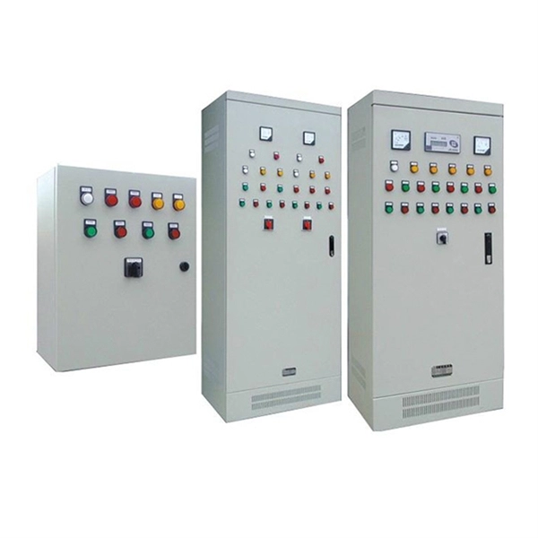
[PDF Version]Contact us for competitive quotes on any of our power communication and smart grid products
Get a Quote