
If possible, remove and reinstall the optical modules to check whether the fault is rectified. Check whether the information is consistent with the optical module specifications provided in the product documentation. Please select a product to check article relevancy This is for Layer 1 connectivity, if the link shows "up/up," but expected traffic is not. If you have physical access to the switch, it can save time to look at the port LEDs which give you the link status or can indicate an error condition (if red or orange). Perform a. I want to connect it to my switch, which is a Ubiquiti usw-pro-aggregation, on an SFP28 port. The client is Windows Server 2022. 0, which came from the Intel v28 release package. If I use a SFP28 DAC cable between the.
This method uses rivets to join busbars by creating holes in the bars and securing them together. It offers a tight and cost-effective joint. Welding techniques, including traditional welding and braze welding, are used to firmly join busbars, providing superior and continuous. If you've ever wondered how to achieve a flawless busbar installation, you're in the right place. Designing a substation involves not only the visible equipment and ratings but also the less apparent factors—operational. This guide provides a complete breakdown of the standardized process for high and low voltage switchgear installation. We'll detail every key step, from initial preparation to final checks. Furthermore, we'll explore unique considerations and specific nuances for projects in Europe, the Americas. A busbar is a common electrical junction point used to consolidate multiple wires, acting as a central hub for power distribution.
[PDF Version]
This article examines common methods for installing indoor optical fiber and outlines the requirements for the job. OPGW, all-dielectric self-supporting cable, and OSFP 400G transceivers are part of modern SDGI, so we'll also discuss it. If you're unfamiliar with the fundamental concepts of fiber optic technology, we recommend reading our. Running fiber internally involves extending this high-speed link from the service entry point to a centralized location, such as a dedicated media closet or network rack. As our reliance on fast, reliable internet connectivity grows, so does the importance of. Today, countless households, offices, and data centers utilize fiber optic cables to transmit large volumes of data quickly and securely. However, the performance of a network depends primarily on the quality of its installation. They fit standard 19” and 23” racks. Rack trays require an insert panel for connecting cables.
[PDF Version]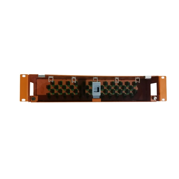
Connecting fiber optic cable takes the right tools, a steady hand, and a few simple steps: prep the fiber, make a clean join with a splice or connector, and test the link for signal quality. This article will guide you through the necessary tools, materials, and methods on how to connect fiber optic cables effectively. This guide will explain the entire set of activities involved in installing Fiber optic cable contractors -from the early planning stage right through testing-for facility managers, IT teams, and low-voltage contractors to build high-performance networks safely and efficiently. Why Use Fiber Optic Internet? Before diving into the setup, let's quickly recap why fiber optics are worth the effort: Lightning-fast speeds (up to 1 Gbps or higher). Before you start, gather the right tools. You don't want to dig around mid-job for something small but essential. Each tool helps you protect the fiber.
[PDF Version]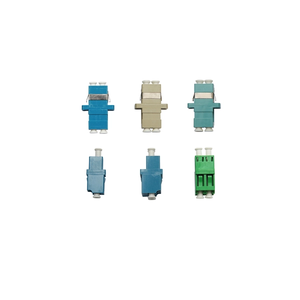
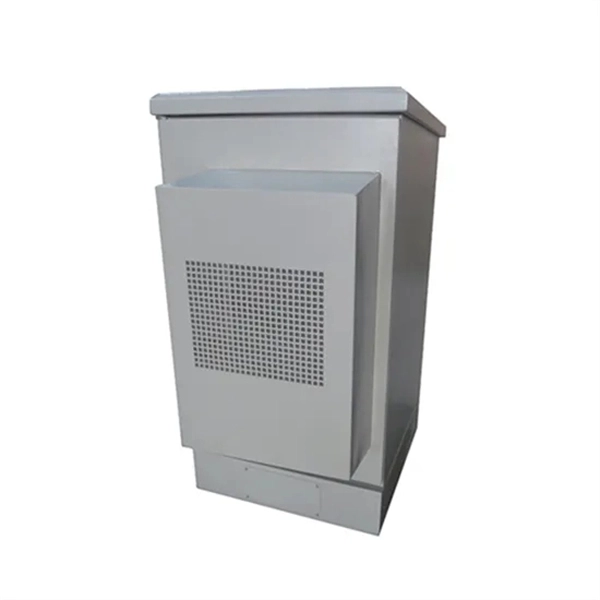
Push a length of UF (underground feed) electrical cable into the conduit, then feed the end of the cable through the hole in the wall. Pull the cable all the way to the main electrical panel. In this video, we'll walk you through the process of wiring a home distribution box with a detailed connection diagram. If needed, rent a gas-powered trenching machine to reduce the amount of manual labor needed. It is mainly used to isolate fault circuits, prevent overload, and ensure the safe operation of. Buried conduits and ducts: Which conduits and ducts offer equivalent mechanical protection to armoured cables when buried in the ground? By: Michael Peace CEng MIET MCIBSE The use of unarmoured cables, such as HO7RN-F rubber flexible cables or unarmoured XLPE cables buried in the ground, is. cify the duct bank to be used. All primary cable installations and feeders larger than No. Any. The in-ground installation for CANTEX PVC junction boxes is also simple, but always be sure to follow all national and regional electrical codes when installing any electrical junction box.
[PDF Version]
A fiber-optic patch cord is a fiber-optic cable capped at each end with connectors that allow it to be rapidly and conveniently connected to telecommunication equipment. This is known as interconnect-style cabling. General characteristicsA fiber-optic patch cord is constructed from a core with a high, surrounded by a coating with a low. Patch cords are classified by transmission medium, connector construction, and construction of the connector's inserted core cover. Single-mode fiber is generally yellow, with a blue conne.
Attach a #6 AWG copper ground wire and ground lug together. In a line-up of more than one. Recommendation ITU-T L. 151 refers to the installation of optical fibre ground wire cable. It deals with the factors that should be considered in determining the characteristics of this type of cable, the apparatus that should be used, the precautions that should be taken in handling the reels, and. Power from factory ground must be installed by a qualified electrician. This position is the connection point of the grounding wire in the. Follow these steps at each cable entry point and termination location to achieve a compliant, safe ground bond: Identify metallic components. Strip back approximately 6–8 inches of the outer jacket using a cable slitter or ringing tool. Visually identify armor, strength members, or foil layers. The basic rule achieves this through an equipment grounding jumper; four exceptions.
[PDF Version]
Inside the service housing, line conductors from the utility feed typically enter through the top and connect directly to dual-lug terminals. Before beginning, locate the correct. Now let's see how to wire a single phase, 230V dual split load consumer unit protected by two RCD's in home. Components Required: A Two Poles Main Switch MCB. 2 No of Two Poles RCD (Residual Current Device). Whether you're an electrician or a DIY enthusiast, this tutorial will help you understand the fundamentals of wiring a. Always begin with disconnecting the main supply before accessing any enclosure containing distribution components. This prevents arc faults and ensures safety when modifying or inspecting current paths. Included are arrangements for 2 receptacles in one box, a switch and receptacle outlet in the same box, and 2 switches in the same box. Single Phase Distribution Box generally consists of Double Pole MCBs, Single Pole MCBs, and RCCBs.
[PDF Version]Contact us for competitive quotes on any of our power communication and smart grid products
Get a Quote