
If possible, remove and reinstall the optical modules to check whether the fault is rectified. Check whether the information is consistent with the optical module specifications provided in the product documentation. Please select a product to check article relevancy This is for Layer 1 connectivity, if the link shows "up/up," but expected traffic is not. If you have physical access to the switch, it can save time to look at the port LEDs which give you the link status or can indicate an error condition (if red or orange). Perform a. I want to connect it to my switch, which is a Ubiquiti usw-pro-aggregation, on an SFP28 port. The client is Windows Server 2022. 0, which came from the Intel v28 release package. If I use a SFP28 DAC cable between the.
Connect Switch with a corresponding fiber device through a fiber cable, or connect with a Media Converter and change to electrical signal for output. Users could choose to use the SFP fiber port or electrical port of the Switch according to different conditions;Equipped with eight SFP+ ports, two additional SFP28 ports and one RJ45 console port for configuration. With AXIS D8308 Fiber Aggregation Switch you can connect multiple Axis devices using fiber midspans over long distances. Simply put, it defines how network. This article reviews essential features as well as benefits and technical specifications associated with an 8 port sfp optical switch, thus giving you a complete idea of how it works in modern networking environments. Whether you work as an IT professional or have an interest in technology only. This SR8 multimode, parallel, 8-channel transceiver uses two, 4-channel MPO-12/APC optical connectors at 400Gb/s each. The parallel multimode, short reach 8-channel (2xSR4) uses 100G-PAM4 modulation and has a maximum fiber reach of 50-meters using 8 multimode fibers. Cisco Catalyst 1000 Series switches provide support for the.
[PDF Version]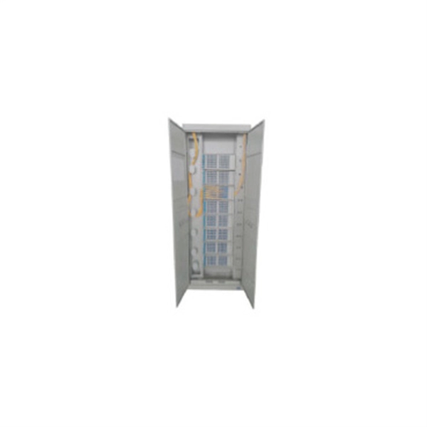
99% of the time, the problem is fiber polarity — specifically, Transmit (Tx) talking to Transmit and Receive (Rx) talking to Receive instead of Tx ↔ Rx. Good news: it's incredibly easy to understand and fix once you know the “two-lane highway” rule. In addition, fiber cables can transmit data over several kilometers without signal degradation, making them ideal for connecting switches in large campus networks and between different buildings. There are no specific requirements for this document. This includes Doppler. Fiber optic networks are celebrated for their speed and reliability, but even the best systems can encounter problems. Switch A is on the router end, devices connected to this switch get DHCP leases and can browse the internet without issue.
Choose an SFP/SFP+ transceiver module compatible with your fiber optic cable type (e. Plug the fiber optic cable into the appropriate connector on the SFP/SFP+ . As a leading provider of fiber optic solutions, Weunion offers a wide range of SFP-compatible products, including optical transceivers, DAC/AOC cables, LC patch cords, and MPO/MTP assemblies. This guide explores the essentials of SFP connectivity, installation best practices, and how Weunion's. Today, we will discuss the best methods to connect SFP to fiber optic patch cables. To connect a fiber optic cable to SFP optical module, first ensure the SFP is fully inserted into the network port until it "clicks", then remove the dust caps from both the SFP and the LC fiber optic connector. Ethernet ports are designed for copper cables (like Cat5e or Cat6), which transmit data using electrical signals. Fiber provides: Increased internet signal bandwidth. The division into OM1, OM2, OM3, OM4 (and also OM5) helps sort out their technical characteristics, such as core diameter, bandwidth and.
[PDF Version]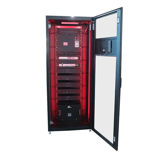
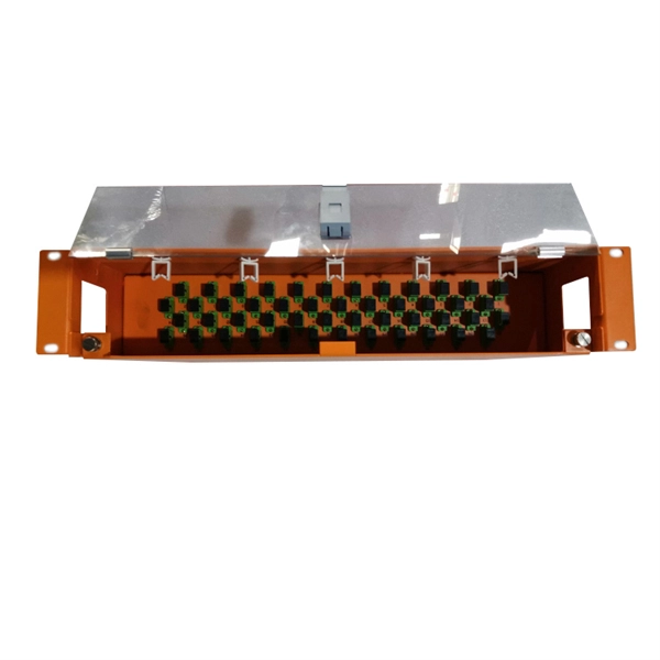
Here's a quick guide on how to install one: ✅ Step 1: Mount the Patch Panel Secure the patch panel into your network rack or wall mount bracket. ✅ Step 2: Run Your Ethernet Cables Pull your Cat5e/Cat6 cables from each wall outlet or device location to the back of the. By automating the process of patching (connecting network equipment via patch cords), Intelligent Patching increases operational visibility and accuracy, while reducing manual errors and downtime in mission-critical environments like data centers. What is Intelligent Patching? At its core. We recommend to equip the entire patch panels with intelligent electronic and use intelligent patch cords in order to keep an eye on the real-time monitoring of the port states. If a. Connecting a patch panel involves organizing and terminating network cables for easier management and connectivity; the process focuses on punching down cables from wall jacks to the panel and then using patch cables to connect devices to your network. The punch-down kit should include the following: That's the full list. If you have everything you need, you're ready to start wiring the panel.
[PDF Version]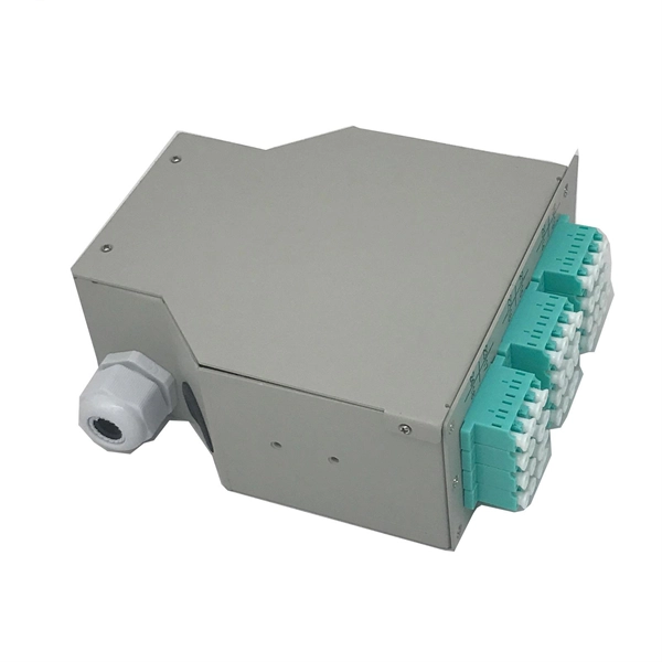
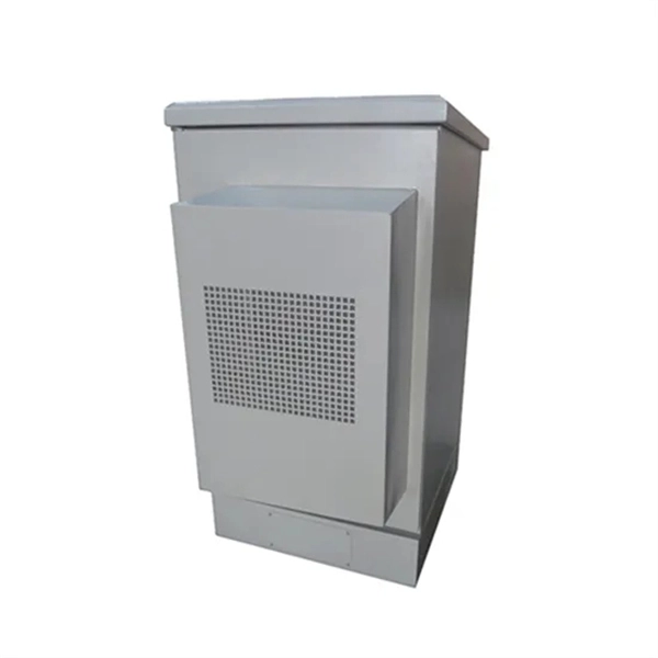
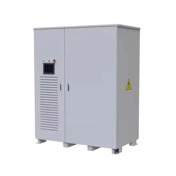
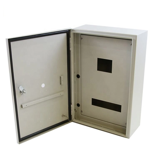
Attach a ground wire from one of the threaded studs (A) at the bottom of the housing, to the mounting plate (B). The ground resistance between all system parts shall be < 0. This position is the connection point of the grounding wire in the. Power from factory ground must be installed by a qualified electrician. Each DISTRIBUTION BOX and controller must be grounded. When inspecting the interior of a stainless steel outdoor electrical box distribution box, pay attention to the copper or tin-plated terminals on the base plate or side walls. Make sure all tools are intact to prevent accidents during the grounding.
This method uses rivets to join busbars by creating holes in the bars and securing them together. It offers a tight and cost-effective joint. Welding techniques, including traditional welding and braze welding, are used to firmly join busbars, providing superior and continuous. If you've ever wondered how to achieve a flawless busbar installation, you're in the right place. Designing a substation involves not only the visible equipment and ratings but also the less apparent factors—operational. This guide provides a complete breakdown of the standardized process for high and low voltage switchgear installation. We'll detail every key step, from initial preparation to final checks. Furthermore, we'll explore unique considerations and specific nuances for projects in Europe, the Americas. A busbar is a common electrical junction point used to consolidate multiple wires, acting as a central hub for power distribution.
[PDF Version]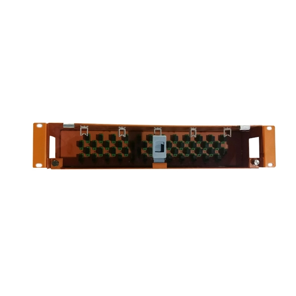
Connecting fiber optic cable takes the right tools, a steady hand, and a few simple steps: prep the fiber, make a clean join with a splice or connector, and test the link for signal quality. This article will guide you through the necessary tools, materials, and methods on how to connect fiber optic cables effectively. This guide will explain the entire set of activities involved in installing Fiber optic cable contractors -from the early planning stage right through testing-for facility managers, IT teams, and low-voltage contractors to build high-performance networks safely and efficiently. Why Use Fiber Optic Internet? Before diving into the setup, let's quickly recap why fiber optics are worth the effort: Lightning-fast speeds (up to 1 Gbps or higher). Before you start, gather the right tools. You don't want to dig around mid-job for something small but essential. Each tool helps you protect the fiber.
[PDF Version]
The ideal structure for connecting two fiber cables is as follows: Cable A → Adapter Panel → Patch Cord → Adapter Panel → Cable B How It Works Fiber Adapters: Bridge the two connector types (e., SC to LC, or SC to SC). Patch Cords: Provide a short, flexible link between adapters. To connect two optical fibers together, a process called splicing is used. This involves aligning the two fiber ends and then fusing them together using heat or a specialized tool. Fiber cabinets, patch panels, and distribution frames are designed to manage and protect terminations, not for direct splicing. Data Servers are at Location A.
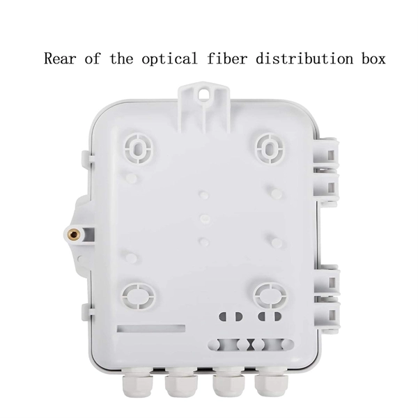
It connects the distribution fiber optic cable and FTTH cables. Normally it's set in doutdoor and installed on poles or walls. An optical distribution box can have 24 port, 16. The optical fiber distribution box allows people to easily access the optical fibers in the box, and can well protect the optical fibers. This includes carefully inspecting each cable for any signs of damage or wear and cleaning their. The Leviton HDF3168 Fiber Distribution System is an optical distribution frame that is designed for the high-density applications in the Main Distribution Area of Data Centers. Whether you're a network technician, IT professional, or simply looking to understand fiber optic networks. According to the definition of YD/T 988-2015, the fiber cabinet is an interface device used to connect the main fiber optic cable andhttps://pna-fiber.
Contact us for competitive quotes on any of our power communication and smart grid products
Get a Quote