
The IEC has published a new standard for the testing of fibre optic cabling. IEC 61280-4-5 provides test methods to measure the attenuation of installed multimode and single-mode optical fibre cabling plant as well as the determination of their polarity and length. Fiber optic testing of a newly installed system not only verifies that the system meets its design requirements, but also creates a performance baseline for all future testing and troubleshooting of t at system. Corning recommends that all fiber optic systems be tested to a minimum set. for installing electrical products and systems. NEIS® are intended to be referenced in contrac documents for electrical construction ation or liability to users of this publication. Lower attenuation means less signal loss over distance. Patch cords and jumper cables must meet stricter performance requirements because connectors. ANSI/TIA‑568.
[PDF Version]
In this blog post, we'll take a deep dive into the key performance tests for fiber optic patch cords — polarity verification, insertion loss and return loss measurement, 3D interferometric endface metrology, and endface inspection — along with the relevant standards . In this blog post, we'll take a deep dive into the key performance tests for fiber optic patch cords — polarity verification, insertion loss and return loss measurement, 3D interferometric endface metrology, and endface inspection — along with the relevant standards . One of the key performance indicators of a fibre optic patch cord is its insertion loss. Insertion loss refers to the reduction in power density (signal) that occurs when a signal is transmitted through the patch cord. This article explains their concepts, standards, testing methods, and FiberMania's quality assurance workflow to ensure optimal network performance. Fiber optic patch cords are crucial components in. Insertion Loss (IL) is one of the most fundamental performance indicators in fiber optic networks.
[PDF Version]
Testing results from tools like OTDRs, power meters, and visual fault locators provide valuable data on the health of a fiber optic network. High loss readings, for example, might indicate problems like breaks, bends, or poor connections. Fiber optic communication offers several advantages over other transmission methods, such as copper cables and traditional data communication techniques: Long-Distance Transmission: Signals can be transmitted over extended distances (approximately 200 km) without requiring signal regeneration. System performance is typically evaluated on an individual link basis between any two given nodes of the. Fiber Optic Testing Testing is used to evaluate the performance of fiber optic components, cable plants and systems. Why Does Fiber Optic Testing Matter? Fiber internet offers better speed and performance than copper options, but the cables are very sensitive to bending, contamination, and physical. Fiber optic networks are the backbone of modern telecommunications, providing high-speed data transmission over long distances with minimal loss. This is why. nal electrical signal at the receiver.
[PDF Version]
A pigtail is used to provide fiber optics with a connector. This creates a stable and reliable. Fiber pigtails are simple in appearance, yet essential in function. They are the bridge between fiber optic cables in the field and the equipment or patch panels that manage them. Get the wrong connector type, the wrong polish, or skip proper fusion splicing technique—and you're looking at elevated signal loss, increased back reflection, and a. A fiber optic pigtail is a short optical fiber cable that has a connector on one end and an exposed (unterminated) fiber on the other.
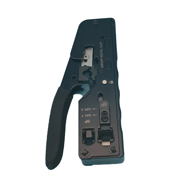
Fiber Optic cable termination is the addition of connectors to each optical fiber in a cable. However, if you're new to the world of fiber optics, you might wonder what it means to terminate fiber optic cables and why it's important. In this. This guide provides a detailed roadmap for locating and fixing fiber optic cable breaks, covering detection techniques, repair methods, and best practices.
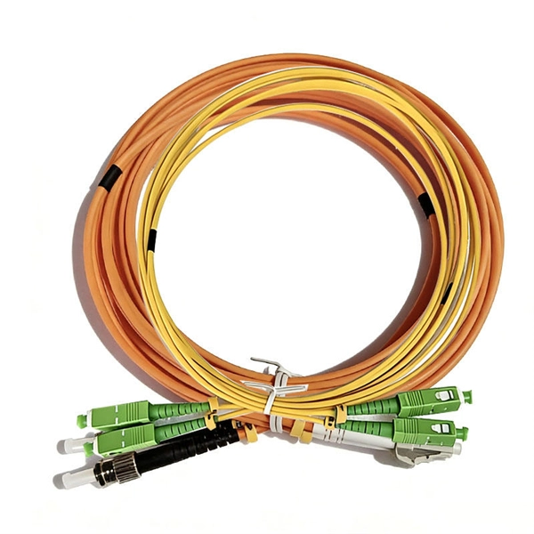
A fiber optic pigtail has a connector only on one end, leaving the other end free, whereas a fiber patch cord has connectors on both ends. The connector end is polished and tested under factory conditions, ensuring low insertion loss and high return loss. Characterized by having an optical fiber connector on one end and a bare fiber end on the other, they are primarily used to connect optical transceivers or other optical. A fiber optic pigtail is usually a fiber optic cable with pre-terminated connectors at one end and exposed fibers at the other.
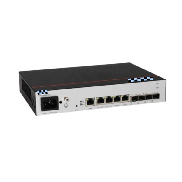
An uplink port generally means a port used that connects toward the core of the network. In this particular usage, the switch's downlink ports are dual speed copper ports. RJ45 ports serve access-layer copper connections; SFP/SFP+ ports enable flexible 1G/10G uplinks; SFP28 delivers 25G for modern data centers; QSFP+ and QSFP28 support high-density 40G/100G spine–leaf. So, the uplink port connects the switch to other switches or “higher” layer routers. Switch normal ports, also known as. The SFP port is commonly found on Gigabit Ethernet switches and is primarily used for fiber optic device connections or for uplinking 1G switches to aggregation/core layer devices, providing higher-bandwidth links. Switch port type should be configured according to the requirement considering the factors like network architecture, speed and. Cisco switch ports are categorized by their physical hardware interfaces (such as RJ45 copper, fiber-optic SFP uplinks, and console ports), their bandwidth speed capacities (Gigabit, 10G, 100G), and their logical operating modes.
[PDF Version]Contact us for competitive quotes on any of our power communication and smart grid products
Get a Quote