
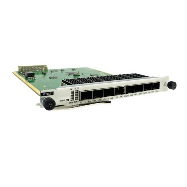
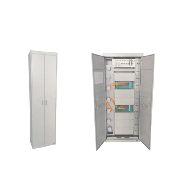
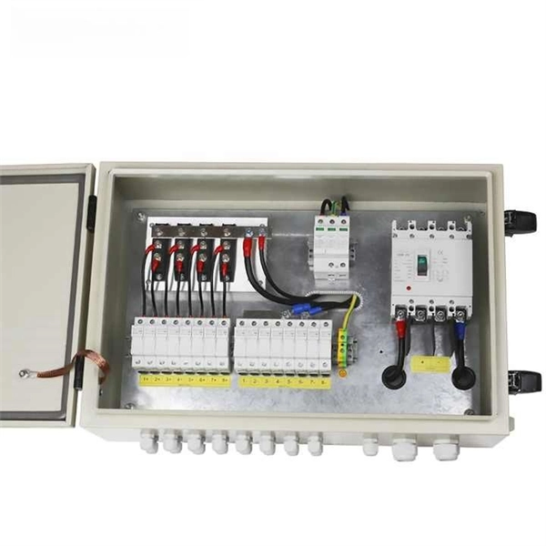
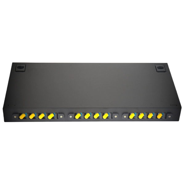
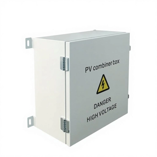
Our splice boxes are used to securely connect and distribute fibre optic cables by protecting spliced glass fibres from external influences. Price and other details may vary based on product size and color. The front panel is provided with additional holes to fix the adapter with screws. The cover h Faber fibre splice boxes are telescopic. AFL offers robust fiber optic splice closures—including Apex® high-density and LightGuard® weathertight and sealed models—for above-ground, aerial, and buried applications.
A main drawback is the complexity of testing and troubleshooting, as well as the need for detailed GIS records to accommodate splitter placement. Training can also be challenging for those unfamiliar with this architecture. Centralized splits typically use higher fiber count cables than distributed split networks, increasing both material and splicing labor costs. Another disadvantage is the aesthetic impact of the PON. A GPON splitter is a passive optical device that takes a single fiber input and splits it into multiple outputs, typically in ratios like 1:2, 1:4, 1:8, 1:16, 1:32, and 1:64. The splitting process introduces signal attenuation, making placement strategy critical for network performance. PON, developed in the mid-1990s, was originally designed to allow internet service providers (ISPs) to deliver broadband triple-play services (data, voice, and video) to residential users. By dividing a single optical signal from a central Optical Line Terminal (OLT) into multiple outputs for Optical Network. Morgan said the downside is that there is “a little bit less ability to troubleshoot” because the terminals are not all in one place. “This is becoming more popular for.
[PDF Version]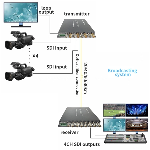
The beam splitter splits and then recombines infrared radiation, while the detector picks up the resulting signal. It's sensitive to both intensity and frequency. Together, they decide just how accurately an instrument captures those unique infrared “fingerprints” from different. A beam splitter or beamsplitter is an optical device that splits a beam of light into a transmitted and a reflected beam. It is a crucial part of many optical experimental and measurement systems, such as interferometers, also finding widespread application in fibre optic telecommunications. In its. Thorlabs' Single Mode Fiber-Based Polarization Beam Combiners (PBC) or Splitters are designed to either combine two orthogonal polarizations into a single fiber or split a single input into its orthogonal linear polarizations through two fiber outputs. The device utilizes birefringence, which is the property of certain materials.
[PDF Version]
A passive splitter does exactly what its name implies: it splits a signal without using any external power. Whether you're dealing with fiber optic networks, HDMI video systems, or RF distribution, splitters help ensure that your signal reaches multiple endpoints efficiently. Typically, but not always, there is one input in and multiple outputs. Some examples: A coupler can be used as a splitter to couple out some portion of the light circulating in the resonator of fiber laser, for example. Directional 2 × 2 couplers (see Figure 1) are usually used for.
To reduce loss of light due to absorption by the reflective coating, so-called "Swiss-cheese" beam-splitter mirrors have been used. Originally, these were sheets of highly polished metal perforated with holes to obtain the desired ratio of reflection to transmission.OverviewA beam splitter or beamsplitter is an that splits a beam of into a transmitted and a reflected beam. It is a crucial part of many optical experimental and measurement systems, such as In its most common form, a cube, a beam splitter is made from two triangular glass which are glued together at their base using polyester,, or urethane-based adhesives. (Before these synthetic,.
Beam splitters are sometimes used to recombine beams of light, as in a. In this case there are two incoming beams, and potentially two outgoing beams. But the amplitudes of the two outgoing beams are the sums of the (complex) amplitudes calculated from each of the incoming beams, and it may result that one of the two outgoing beams has amplitude zero. In order for ener.
It is an optical fiber tandem device with many input and output terminals, especially applicable to a passive optical network (EPON, GPON, BPON, FTTX, FTTH etc. An optical splitter is a crucial passive fiber optic device that splits and combines optical signals. All the fibers are epoxied together at the nexus of the. Optical splitters and couplers split or combine light—distributing signals injected into a single fiber strand to multiple fibers, enabling point to multi-point communication in Fiber To The Home (FTTH) networks based on ITU. The fiber optic. Global Foxcom's PL7602 is a passive two-way optical splitter/combiner for Sat-Light/Platinum deployments. Rarely, there can be two inputs to provide potential redundancy of route. Light power goes in and light power coming out of the various legs is reduced in.
Testing a splitter or other passive fiber optic devices like switches is little different from testing a patchcord or cable plant using the two industry standard tests, OFSTP-14 for double-ended loss (connectors on both ends) or FOTP-171 for single-ended testing. Optical splitters are usually used in passive optical networks (PONs) to distribute fiber to individual homes or businesses. In this. Testing networks with both an optical loss test set (OLTS) or OTDR is covered in other pages on Testing FTTH PONs and Testing Passive OLANs. This note also provides background information on system link configurations, test equipment and system component considerations that influence. In fiber optic networks, particularly in FTTx (Fiber to the x) and PON (Passive Optical Networks) deployments, splitters play a central role in distributing the optical signal from a single source to multiple destinations.
[PDF Version]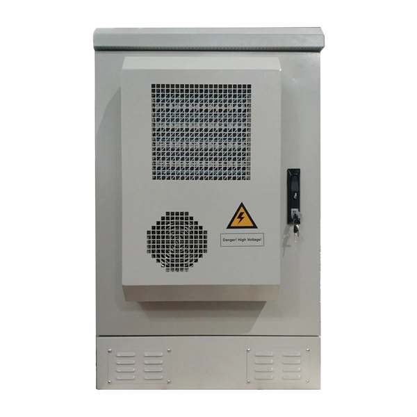
For beam splitters with two incoming beams, using a classical, lossless beam splitter with Ea and Eb each incident at one of the inputs, the two output fields Ec and Ed are linearly related to the inputs through where the 2×2 element is the beam-splitter transfer matrix and r and t are the and along a particular path through the beam splitter, that path being indicated by the subsc.
Contact us for competitive quotes on any of our power communication and smart grid products
Get a Quote