
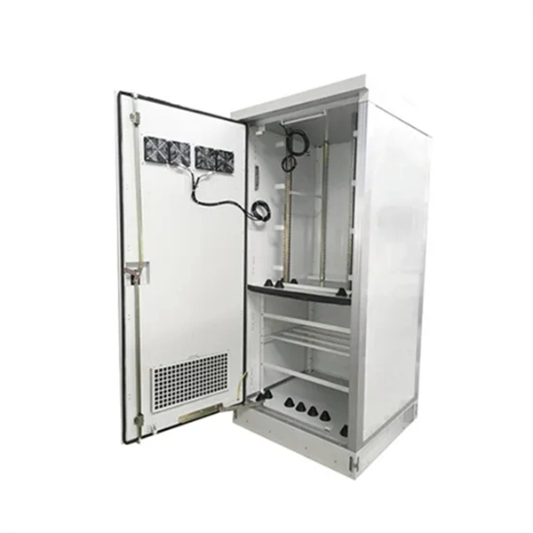
An Optical Distribution Frame (ODF) is a central hub in fiber optic networks, crucial for managing and organizing the myriad of fiber optic cables and connections entering a facility. Unlike standard racks and fiber optic panels, they are modular and agile, specifically designed for today's fast. Austin Hughes ODF (optical fibre distribution frame) is designed with highest capacity and superior cable management. This lightweight rack is made of aluminum and has 19” or ETSI profiles that allow flexible height adjustment when you install an ODF system. It's small footprint, and front access enables floor space to be utilised by revenue. The Cable Distribution Rack (CDR) is a purpose-built, high-density fiber management rack that functions as a central cross-connect in the primary distribution area of data centers. With a footprint depth of only 300 mm, the CDR is fully modular and scalable.
[PDF Version]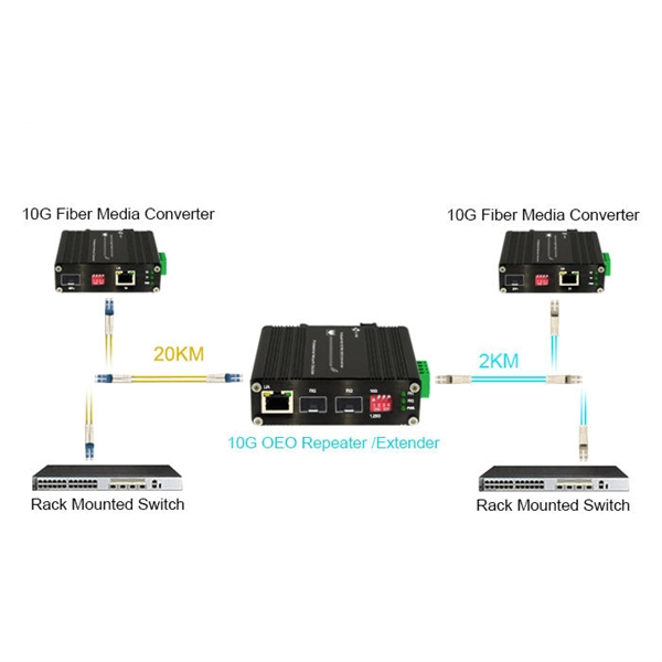
ODF series indoor optical fibre distribution box is used in the terminal access link of FTTH system,It is a device that splices, distributes, and splits optical fibres and provides protection and management of optical fibres. ODF series are standard 19 "rack mount chassis with. An ODF is a centralized platform designed for terminating, cross-connecting, and managing optical fibers. This lightweight rack is made of aluminum and has 19” or ETSI profiles that allow flexible height adjustment when you install an ODF system.
Full-spectrum single-mode fibre in accordance with ITU-T G. D with optimised transmission characteristics. 652 fibre was originally optimized for use in the 1310 nm wavelength region but can also be used in the 1550 nm region. a number of concatenated cable. “Leviton is dedicated to designing, developing and manufacturing sustainable high performance structured cabling and specialty cabling solutions. ” The information contained in this document is valid and correct at the time of issue. 1dBNote: Due to OTDR measurement uncertainty B3 International cannot guarantee attenuation values at fibres shorter than 1000m. Specifications are for product as supplied by Prysmian: any modification or alteration afterward of product may give different result.
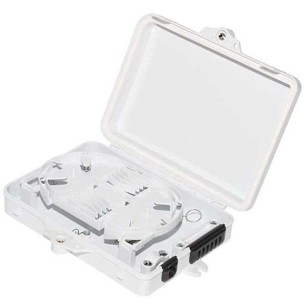
Position the fibers accurately and apply slight tension in the V-grooves. Check visually; follow up with a mechanical pull test and an optical loss test on the finished splice. Securely install and heat. Regardless of your level of experience, creating high-quality, high-performance fiber optic networks requires developing your skills in fusion splicing. This guide reveals the secrets to fusion splicing with little fluff—just proven, straightforward techniques refined from years of work in the. Thorlabs' Vytran® product family is designed for fusion splicing, optical fiber processing, and end face geometry inspection. To create splices with high optical quality and mechanical strength, these tools perform a series of tasks, including stripping, cleaning, cleaving, splicing, recoating, and. The fusion splicer performs optical fiber fusion splicing in two steps. Precisely align the two fibers 2. PRECAUTIONS For. Fusion splicing is the process of fusing or welding two fibers together usually by an electric arc. Required Tools & Equipment - Fiber optic fusion splicer - Cleaver & stripper - Splice tray and enclosure - Cleaning kit (alcohol, lint-free wipes) -.
[PDF Version]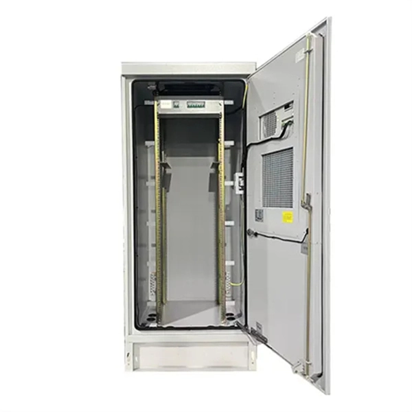
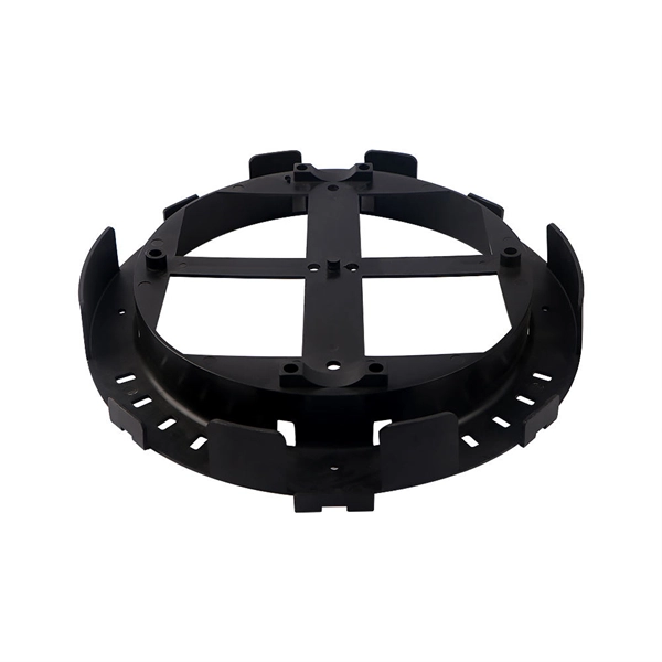
PLC splitters offer a better solution for larger applications. Waveguides are fabricated using lithography onto a silica glass substrate, which allows for routing specific percentages of light. As a result, PLC splitters offer accurate and even splits with minimal loss in an efficient package.OverviewA fiber-optic splitter, also known as a, is based on a of an integrated waveguide power. According to the principle, fiber optic splitters can be divided into Fused Biconical Taper (FBT) splitter and Planar Lightwave Circuit (PLC) splitters. The FBT splitter is one of the most common. F. Wave splitting involves dividing a light beam into multiple streams. The daughter streams can be equal or in some other ratio. The FBT splitter uses two (or more) fibers. The fibers'. • The FBT splitter offers low cost, common materials (quartz substrate, stainless steel, fiber, hot dorm, GEL), and an adjustable splitting ratio. However, its losses are wavelength-dependent and it offers poor spectral uni.
[PDF Version]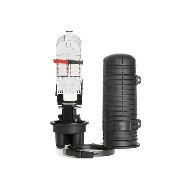
The SFP-10G-AOC SFP+ Active Optical Cable is a plug-and-play, cost-effective solution for 10Gbps connections. It uses Multi-Mode Fiber (MMF) with SFP+ connectors and has built-in optics, eliminating the need for separate transceivers and patch cables. A 10G SFP+ AOC offers a straightforward, high-performance means of interconnecting two 10-gigabit ports—efficiently and without the complexity of separate optics and fiber. The overview below explains the essentials in clear terms. This AOC is compliant with SFF-8431 MSA standards. Key characteristics include: Integrated Optics and Electronics: Embedded transceivers at both ends handle conversion between electrical 10 GbE signals. A MANUFACTURER - 14 years ISO certified manufacturer, assembly SFP transceiver, fiber patch cords, media converter and networking system. ESD This transceiver is specified.
An uplink port generally means a port used that connects toward the core of the network. In this particular usage, the switch's downlink ports are dual speed copper ports. RJ45 ports serve access-layer copper connections; SFP/SFP+ ports enable flexible 1G/10G uplinks; SFP28 delivers 25G for modern data centers; QSFP+ and QSFP28 support high-density 40G/100G spine–leaf. So, the uplink port connects the switch to other switches or “higher” layer routers. Switch normal ports, also known as. The SFP port is commonly found on Gigabit Ethernet switches and is primarily used for fiber optic device connections or for uplinking 1G switches to aggregation/core layer devices, providing higher-bandwidth links. Switch port type should be configured according to the requirement considering the factors like network architecture, speed and. Cisco switch ports are categorized by their physical hardware interfaces (such as RJ45 copper, fiber-optic SFP uplinks, and console ports), their bandwidth speed capacities (Gigabit, 10G, 100G), and their logical operating modes.
[PDF Version]Contact us for competitive quotes on any of our power communication and smart grid products
Get a Quote