
Dirty Fibers: Dust, oil, and residue reduce splice quality. Misalignment: Incorrect positioning of fibers leads to light leakage. Worn Electrodes: Old or contaminated electrodes. A single imperfect splice can disrupt connectivity for businesses, schools, and homes, causing slow speeds, intermittent outages, and costly downtime. Whether it's from misalignment, dust contamination, environmental stress, or poor splice protection, these problems can quickly escalate if not. This guide reveals the secrets to fusion splicing with little fluff—just proven, straightforward techniques refined from years of work in the field. These minimal losses add up to significant differences in range and signal quality across an entire network. When properly maintained and operated, they produce low-loss, high-strength splices. Splicing fiber optic cable is an extremely important phase for making dependable, high-speed communication infrastructures.
[PDF Version]To identify a broken fiber optic cable, start by performing a visual inspection for any physical signs of damage, such as bends, cracks, or breaks...
There are several methods to test fiber optic cables without a tester. One method is using a visual fault locator (VFL), as mentioned earlier, to v...
Intermittent fiber optic connections can be caused by a variety of factors, including: Poorly terminated connectors or splices that result in unsta...
End face contamination negatively impacts fiber optic performance by increasing signal loss, reflection, and scattering. Contaminants such as dirt,...
Fiber optic degradation can be caused by several factors, such as: Physical stress on the cable, including bending, twisting, or crushing, which ma...
When your fiber internet is not functioning, follow these steps to resolve the issue: Verify that all connections are secure and properly seated, i...
In, a single-mode optical fiber, also known as fundamental- or mono-mode, is an designed to carry only a single of light - the. Modes are the possible solutions of the for waves, which is obtained by combining and the boundary conditions. These modes define the way the wave travels through space, i.e. how the wave is distributed in space. Waves can have the same mode but have different frequencies. This is the case i.
The choice between fusion and mechanical splicing for fiber optic splice module installation depends on project requirements, budget and available infrastructure. Fusion splicing is the process of fusing or welding two fibers together usually by an electric arc. The result is a connection which allows light to pass through without being impeded – we call that a. In this guide, you will find a chronological description of the fusion splicing process, the principal technical standards, and answers to the real-life questions network engineers and procurement teams may have. Let's explore the fundamentals of mechanical and fusion.
Quick answer: Industry acceptance threshold for a single fusion splice is 0. 1 dB should be re-done before sealing. Acceptable dB loss for fiber depends on the component you're measuring: a single mated connector pair should lose no more than 0. 5 dB per kilometer depending on the type and wavelength. The total. To be able to judge whether a fiber optic cable plant is good, one does a insertion loss test with a light source and power meter and compares that to an estimate of what is a reasonable loss for that cable plant. The primary contributors to measured splice loss are fiber material and design factors that. Splice loss refers to the part of the optical power that is not transmitted through the splice and is radiated out of the fibre. The total loss in decibels at the fusion splice is given by the following equation, where Pin is the total power incident on the fusion splice and Ptrans is the. When using a fusion splicer, the typical splice loss is usually between 0. However, various factors, such as fibre cleanliness, core. Results from a National Electronics Manufacturing Initiative (NEMI) project, formed to improve aspects of fiber optic fusion splicing, are reported.
[PDF Version]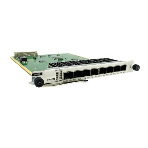
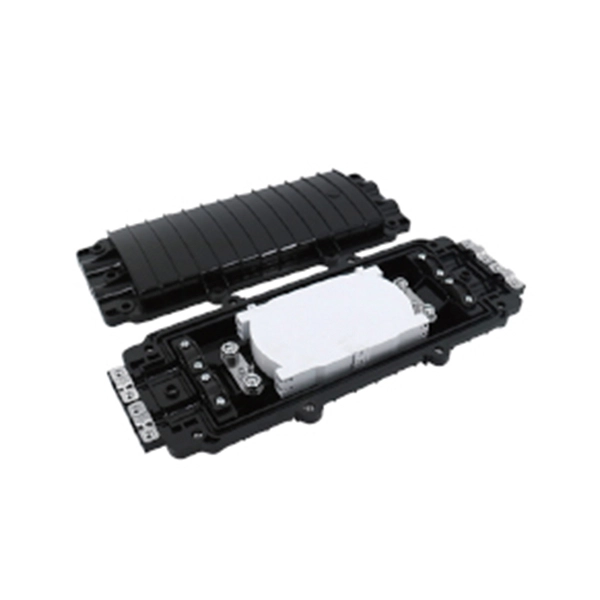
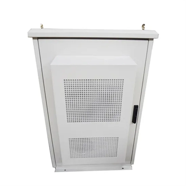
Our splice boxes are used to securely connect and distribute fibre optic cables by protecting spliced glass fibres from external influences. Price and other details may vary based on product size and color. The front panel is provided with additional holes to fix the adapter with screws. The cover h Faber fibre splice boxes are telescopic. AFL offers robust fiber optic splice closures—including Apex® high-density and LightGuard® weathertight and sealed models—for above-ground, aerial, and buried applications.
Learn how to splice fiber optic cable using fusion splicing with this complete step-by-step guide. Includes tools, best practices, loss standards (ITU-T G. 652), cost analysis, and FAQs for network engineers and installers. Regardless of the type of fiber network you're deploying, be it for telecom, enterprise data centers, or smart city infrastructure, fusion splicing provides the benefits of. Splicing allows you to restore or expand fiber networks while maintaining signal integrity. When done right, splicing ensures minimal loss and long-lasting performance. This guide will walk you. 🔧 Watch a real-time fiber optic splicing demo in action! In this step-by-step tutorial, learn how to splice fiber optic cables like a pro — perfect for telecom technicians, network engineers, and field techs.
Splice boxes, also known as fiber optic splice enclosures or fiber splice closures, are essential components in fiber optic networks. Their primary function is to protect and manage the spliced fiber optic cables, ensuring they remain secure, well-organised, and unaffected by. For protection against the outside plant environment and damage, splices require placement in a protective enclosure, usually called a splice closure.
Fiber optic splice closure is a critical element in fiber optic networks as it enables the connection and protection of fiber optic cables. It is an essential component that provides protection and organization for fiber optic splices, ensuring the integrity and reliability of the network. In this article, we will explore the. Splices are generally placed in a splice tray which is then placed inside a splice closure or integrated into a fiber pedestal for OSP installations. For premises applications (indoors) splice trays are often integrated into patch panels or wall-mounted boxes to provide for connections for the. Fiber optic closure is a device used to connect and protect optical fibers, providing optical cables with functions such as wiring, fusion, fiber storage, and protection.
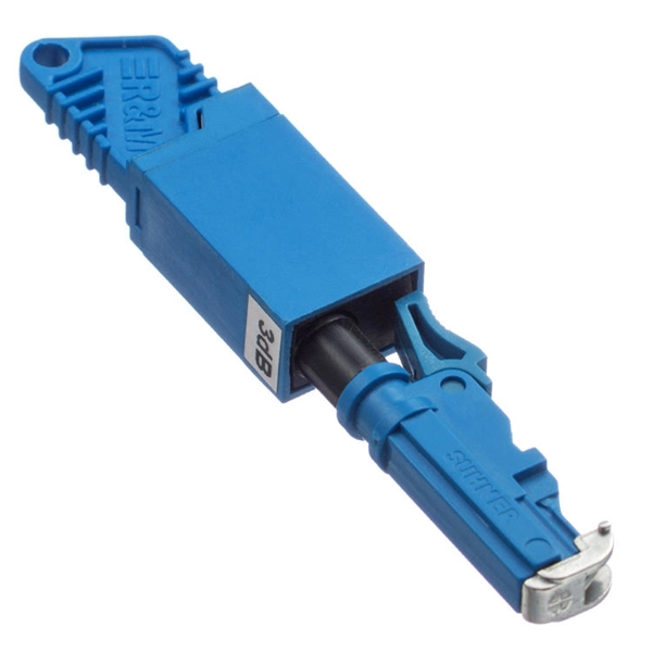
How does an LC optical module dust plug prevent fiber optic contamination? It blocks dust from entering SFP ports, maintaining signal integrity and protecting optical lenses by providing a secure, sealed cover when ports are not in use. Disclaimer: This content is provided by third-party. Used in Optical Fiber Communication Transceiver Modules SFP, SFP+, QSFP, QSFP28,GBIC and Other Products;. Please let me know the angle you need and all your requirements, such as whether you want burned balls, gold plating, and whether you want nickel tube assemblies, etc.
Optical fiber cold splice technology is based on the use of mechanical connectors to join two fiber-optic cables. In this guide, you will find a chronological description of the fusion splicing process, the principal technical standards, and answers to the real-life questions network engineers and procurement teams may have. Either joining method must have three primary characteristics. Splices are critical points in the optical fibre network, as they strongly affect not only the quality of the links, but also their lifetime. During assembly, no need glue dispensing and polish. The fiber quick splicing connector has two types: straight-through (fiber not. Fiber optic splicing is the process of joining two optical fibers end-to-end. This process is fundamental to building and.
Contact us for competitive quotes on any of our power communication and smart grid products
Get a Quote