
An optical power meter (OPM) is a device used to measure the power in an signal. The term usually refers to a device for testing average power in systems. Other general purpose light power measuring devices are usually called,, power meters (can be sensors or ), or lux meters. A typical optical power meter consists of a , measuring and display. The sens.
About 850 nm wavelength is used for the OSFP 400G DR4 transceiver module which is primarily designed to allow transmission through the multimode fiber (MMF) up to 100m. First, let's clarify what VR, SR, DR, FR, LR, ER, and ZR stand for, so that we can understand and identify them: VR (Very Short Range): Transmission distance usually 0~100 meters, using multimode fiber for short data center connections. This transceiver module features a 4-channel architecture, which allows sending 100 Gbps each to achieve an aggregated total of. NADDOD's 400G DR4/DR4+ & FR4 optical transceivers comply with the IEEE 802. 3cu (Draft) standards and employ a platform-based hardware design. They can meet the transmission requirements of 500m and 2km, respectively. DR4 uses parallel single-mode optics over MPO fiber, while FR4 and LR4 rely on CWDM wavelength multiplexing over. The 400G electrical signal is also split into four signals, but the difference is that in FR4, each signal drives a laser operating at a different central wavelength (such as 1271nm, 1291nm, 1311nm, 1331nm).
[PDF Version]
2, published in 2002, defines that a CWDM system can support up to 18 nominal center operating wavelengths over a fiber link, ranging from 1270 nm to 1610 nm. Adjacent wavelengths are spaced 20 nm apart, with an allowable center wavelength deviation of. The first edition of ITU-T G. Various lasers, including those of the same kind, may have different center. Thank You!Center Wavelength: The center wavelength of optical modules refers to the range of light waves utilized during the transmission of optical signals, measured in nanometers (nm). Commonly used wavelengths include 850nm, 1310nm, and 1550nm, as well as the CWDM wavelengths ranging from 1270nm to 1610nm. This document focuses on projection optical modules that incorporate Texas Instruments' DLP Display chips and are designed to project an image onto a surface for a variety of applications, including smartphones, tablets, display projectors, smart home displays, digital signage, AR glasses, and.
[PDF Version]
Synchronous Digital Hierarchy (SDH) is a standardized multiplexing hierarchy for transmitting digital signals over optical fiber networks. It provides a flexible and efficient way to transport large amounts of data with high reliability and synchronization. This tutorial addresses the importance of scalable DWDM systems in enabling service providers to accommodate consumer demand. The protocol used in modern networks to satisfy these cravings is Synchronous Digital Hierarchy (SDH) or the almost identical Synchronous Optical NETwork (Sonet) which is primarily used in the U. At low transmission rates, data can also be. Dense Wavelength Division Multiplexing or DWDM is the method which allows multiple wavelengths to be brought to a single-mode fiber, consequently growing the potential of that particular transmission route by using a factor which is equal to the total number of wavelengths that one has added during. In the realm of telecommunications and high-speed data transmission, Wavelength Division Multiplexing (WDM) and Synchronous Digital Hierarchy (SDH) stand as foundational technologies.
[PDF Version]
In fiber-optic communications, wavelength-division multiplexing (WDM) is a technology which multiplexes a number of optical carrier signals onto a single optical fiber by using different wavelengths (i. This allows multiple channels of data to be transmitted simultaneously. WDM lets you increase capacity and lower latency within your existing footprint. Artificial Intelligence and the Impact on Our Data Centers > WDM technology is at the forefront of mobility network evolution, helping you maximize your fiber utilization to meet customers' ever-increasing, day-to-day. Wavelength division multiplexers are fundamental to the functioning and performance of integrated photonic circuits, with applications ranging from optical interconnects to sensing and quantum technologies. Current solutions are limited by trade-offs between channel spacing, crosstalk, insertion. This section contains examples of wavelength division multiplexing (WDM) circuits. To begin with, we assume that we have the element.
[PDF Version]
Standard Installation: Fiber optic cables are generally buried at depths ranging from 3 to 4 feet (approximately 0. This depth helps protect the cable from damage caused by digging, animals, and environmental conditions like freezing and flooding. In extreme cold climates, cables may need to be buried at greater depths where there temperatures are colder and frost penetrates to. The International Telecommunication Union (ITU) and Institute of Electrical and Electronics Engineers (IEEE) recommend a minimum depth of 0. 6 meters for urban areas and 1. The National Electrical Code (NEC) in the. With international fiber networks predicted to grow to over 1. 8 million km in scope by 2025 (per TeleGeography), burying these cords of light comes with the benefits of avoiding cable damage, decreasing downtime, and extending their operational lifetime. Project success depends on careful planning, precise installation practices, and proper. The short answer, based on general industry standards and the National Electrical Code (NEC), is that fiber optic cable is typically buried between 24 inches (60 cm) and 30 inches (76 cm) deep.
[PDF Version]
Usually, in ordinary soil and hard soil, optical cables need to be buried below 1. During the construction of directly buried optical cables, it is necessary to dig the ground base on the requirements, then lay the buried optical cable to the bottom of the trench, and. This comprehensive guide delves into the installation requirements, explores the two primary cable types—self-supporting and messenger-supported—and offers practical insights to ensure optimal performance in diverse environments. Understanding Overhead Fiber Optic Cable Overhead fiber optic. The Fiber Optic Association, Inc. (FOA) was founded in 1995 to help develop the workforce to build the fiber optic networks to support a rapid expansion in communications and the Internet. The charter of the FOA was to promote professionalism in fiber optics through education, certification, and. Deploying fiber above ground on poles or towers removes the need for underground digging and is particularly useful when the ground is uneven, rocky or both. The pole number should face the road, with black characters on a white background and Arabic numerals as the font.
[PDF Version]
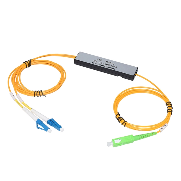
Optical receivers, in contrast to laser sources, tend to be wideband devices. Therefore, the demultiplexer must provide the wavelength selectivity of the receiver in the WDM system. WDM systems are divided into three different wavelength patterns: normal (WDM), coarse (CWDM) and dense (DWDM).OverviewIn, wavelength-division multiplexing (WDM) is a technology which a number of signals onto a single by using different (i.e., colors) of. A WDM system uses a at the to join the several signals together and a at the to split them apart. With the right type of fiber, it is possible to have a device that does both s. Originally, the term coarse wavelength-division multiplexing (CWDM) was fairly generic and described a number of different channel configurations. In general, the choice of channel spacings and frequency in these co.
In fiber-optic communications, wavelength-division multiplexing (WDM) is a technology which multiplexes a number of optical carrier signals onto a single optical fiber by using different wavelengths (i. Read on to learn the fundamentals of this useful technology. Each wavelength, or “channel,” carries an independent data stream, allowing bandwidths up to 400.
WDM systems are divided into three different wavelength patterns: normal (WDM), coarse (CWDM) and dense (DWDM). Normal WDM (sometimes called BWDM) uses the two normal wavelengths 1310 and 1550 nm on one fiber. Coarse WDM provides up to 16 channels across multiple transmission windows of silica fibers. OverviewIn, wavelength-division multiplexing (WDM) is a technology which a number of signals onto a single by using different (i.e., colors) of. A WDM system uses a at the to join the several signals together and a at the to split them apart. With the right type of fiber, it is possible to have a device that does both s.
Contact us for competitive quotes on any of our power communication and smart grid products
Get a Quote