
OTDRs display trace results by plotting reflected and backscattered light versus distance along the fiber, characterizing any reflective and non-reflective events in a fiber link. These reflections, known as Fresnel reflections, are meticulously measured by the OTDR to pinpoint the location of these events within the fiber link. Due to the inherent structure of the fiber and microscopic imperfections within the glass, a small portion of the light pulse scatters in various. An optical time-domain reflectometer (OTDR) is an optoelectronic instrument used to characterize an optical fiber. The OTDR is also commonly used to create a "picture" of fiber optic cable when it is newly installed. However, its value lies not only in taking measurements but also in correctly interpreting the records (traces) it generates.
If damage is found, contact your supplier immediately. Verify that all components listed in the packing slip are present. Before initial use, fully charge the device's internal battery. Connect the provided AC power adapter to the power input port on the device (refer to Figure 3. The EXFO MAX-730D-SM8 is a high-performance Optical Time Domain Reflectometer (OTDR) designed for comprehensive fiber optic network characterization and troubleshooting. No part of this publication may be reproduced, stored in a retrieval system or transmitted in any form, be it electronically, mechanically, or by any other means such as photocopying, recording or otherwise, without the prior writt eved to be accurate and reliable. Ensure that the ambient temperature in the location where you charge the batteries is within the specifications (the battery. The MaxTester 700B/C Series is the first tablet-inspired OTDR line that is handy, lightweight and rugged enough for any outside plant environment. The OTDR is a valuable tool for anyone who works with optical fibers.
[PDF Version]
The NetTest CMA4000 is an advanced OTDR (Optical Time Domain Reflectometer), designed for fiber optic network testing. The CMA4000 Optical Test System is an all-in-one test and measurement solution for network commissioning, fault location/restoration, maintenance, and DWDM spectral analysis. It provides high-resolution measurements, extensive analysis capabilities, and is ideal for troubleshooting optical networks. Here's a link to NetTest_CMA4000_Spec_Sheet. Memory upgrades, color screens, power meter, VFL and software update options available. They characterise the len th, attenuation and return loss (ov se individual events along ink: connection points (splices, connectors), te ng by particles much smaller than the wavelength of the.
The FTB-500 can house any of EXFO's FTB plug-and-play modules, enabling you to reconfigure your test solution as your test needs evolve. Combine physical and optical characterization applications with transport and datacom test modules covering next-generation 10G, 40G and 100G. Fiber OTDR FTB-1 /FTB-500 Optical Time Domain Reflectometer otd price EXFO FTB-1-720 Optical Loss Test Set / Used OTDR Machine / Fiber Inspection Microscope FTB-1 OTDR 1. We locate in Beijing- the capital of China. Right out of multi-application wonderland. More than 15 years professional. Chinese, English, Spanish,Portuguese. We locate in Beijing- the capital. The FTB-500 platform embodies a completely new approach to work: more advanced applications, faster setup, testing and reporting, wireless communication and universal compatibility with all FTB modules from the company EXFO – old, current and future. So go ahead: break new grounds, set new test-performance standards, and tame new technologies. Benefit from an all-in-one platform that you can build around your most.
[PDF Version]
FEC encodes outgoing data with additional bits based on well-defined mathematical rules. The receiver uses these bits to detect and correct a limited number of errors caused by impairments like dispersion, noise, or crosstalk. Block-based codes widely used in Ethernet and. By embedding redundant data that allows receivers to correct errors without retransmission, FEC delivers high-speed performance with low error rates, ensuring both scalability and cost-effectiveness. The addition contains sufficient information on the actual data to enable the FEC decoder at the receiver end to. O-FEC is an advanced forward error correction algorithm based on block turbo codes with soft-decision iterative decoding. Originally developed for the Open ROADM specifications and later adopted by the OpenZR+ Multi-Source Agreement (MSA), O-FEC provides approximately 11 to 11. That's why FEC is vital in situations where delays just aren't an option, like live video streaming, satellite links, or real-time voice calls.
[PDF Version]
Optical fibers are an integral part of modern communication systems, enabling high-speed data transfer and reliable connectivity. They are thin, transparent strands of glass or plastic used to transmit light signals over long distances. Light acts as a carrier wave and can be modulated to carry information. Fiber is preferred. Recent advancements including coherent detection, optical amplification, and fiber-optic sensing are discussed, along with their impact on future networks.
BS EN 60794-1-21 is maintained by GEL/86/1. The current release of this standard is: BS EN 60794-1-21:2015+A1:2020 Optical fibre cables. Basic optical cable test procedures. Mechanical tests methods This standard is available from the following sources:The International Electrotechnical Commission (IEC) is the leading global organization that prepares and publishes International Standards for all electrical, electronic and related technologies. The technical content of IEC publications is kept under constant review by the IEC. An objective of this document is to define general requirements and methodology. Listing of all FOA standards FOA Standard FOA-1: Testing Loss of Installed Fiber Optic Cable Plant, (Insertion Loss, TIA OFSTP-14, OFSTP-7, ISO/IEC 61280, ISO/IEC 14763, etc. IEC 60794-1-2:2021 applies to optical fibre cables for use with telecommunications equipment. Electrical properties are specified for optical ground wire (OPGW) and optical phase conductor (OPPC) cables.
[PDF Version]
The core of a conventional optical fiber is the part of the fiber that guides the light. The core is surrounded by a medium with a lower index of refraction, typically a cladding of a different glass, or plastic. Light. A fiber optic is made of five main parts, labeled in the animation and summary image of Video 1. The numerical aperture. This post will unravel the mystery of fiber optics by exploring their three main layers— core, cladding, and coating —to show you why they're so essential for lightning-fast connections. In the 1960s, due to the advancement of technology and the growth of communication demands, people began to seek new communication technologies.
In this review, we cover the state-of-the-art of optical modulators based on two-dimensional materials including graphene, transition metal dichalcogenides and black phosphorus. Two-dimensional (2D) materials with layered structures have a variety of exceptional electronic and optical attributes for potentially developing basic functions of light wave technology from light-emitting to -modulating and -sensing.
The SFP port is a built-in optical port of a Gigabit Ethernet switch, so it cannot be directly connected with a twisted pair or a jumper. It needs to be connected to an optical module first, and then it can be transmitted with an optical fiber patch cord. This project. This installation note provides the technical specifications and installation instructions for the Gigabit Ethernet Converters (GBICs) that you install in Catalyst 4000 or Catalyst 5000 series Gigabit Ethernet ports that accept GBICs. It uses a double-layer board design + minimal peripheral components to save costs to the maximum extent. In previous lesson, we had discussed about Ethernet (10 Mbps) and FastEthernet (100 Mbps) Straight-through and Cross-over. Ethernet is a family of specifications that governs a few different things: It covers all the different wiring specifications (10BASE-T, 100BASE-TX, 1000BASE-T, etc. ).
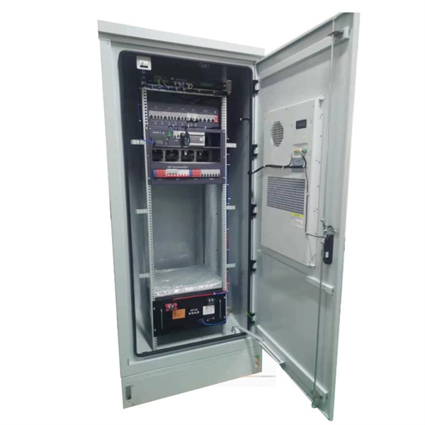
[PDF Version]Contact us for competitive quotes on any of our power communication and smart grid products
Get a Quote