
What is an Optical Switch Module? An optical switch module is an optical device featuring one or more selectable transmission ports, designed to physically switch or logically manipulate optical signals within an optical transmission line or an integrated optical circuit. Thorlabs' offers a selection of optical switches. Also available are. Optical switching is the process of controlling the destination of individual optical information signals. Figure: Optical Switch. POLATIS ® Series 6000 Optical Switch Modules (OSM) are high-performance, fully non-blocking all-optical matrix switch modules with port counts from 16xCC up to 48xCC, offering "any-to-any" port connectivity. 2 dB), fastest switching speed (10 ns), broadest wavelength range (300–2400 nm), widest fiber compatibility, highest optical power handling (50 W), and space-qualified reliability.
Testing a splitter or other passive fiber optic devices like switches is little different from testing a patchcord or cable plant using the two industry standard tests, OFSTP-14 for double-ended loss (connectors on both ends) or FOTP-171 for single-ended testing. First we should define what these. Splitter loss refers to the reduction in optical power that occurs when a single optical signal is divided among multiple output ports in a fiber optic network. Insertion loss testing of the optical splitter is very important to ensure compliance to the optical parameters of the manufactured. Optical splitters are vital components in fiber optic networks, distributing signals from a single input fiber to multiple output fibers. Here is a table of typical losses for splitters. Signal loss within a system is expressed using the decibel. The CertiFiber® Pro Optical Loss Test Set (OLTS) can be used to check that the loss of a PON Splitter (often referred to in various standards as a non-wavelength-selective or wavelength-selective branching device) to check that it is within the allowed defined limits. The CertiFiber® Pro has an.
[PDF Version]
BS EN 60794-1-21 is maintained by GEL/86/1. The current release of this standard is: BS EN 60794-1-21:2015+A1:2020 Optical fibre cables. Basic optical cable test procedures. Mechanical tests methods This standard is available from the following sources:The International Electrotechnical Commission (IEC) is the leading global organization that prepares and publishes International Standards for all electrical, electronic and related technologies. The technical content of IEC publications is kept under constant review by the IEC. An objective of this document is to define general requirements and methodology. Listing of all FOA standards FOA Standard FOA-1: Testing Loss of Installed Fiber Optic Cable Plant, (Insertion Loss, TIA OFSTP-14, OFSTP-7, ISO/IEC 61280, ISO/IEC 14763, etc. IEC 60794-1-2:2021 applies to optical fibre cables for use with telecommunications equipment. Electrical properties are specified for optical ground wire (OPGW) and optical phase conductor (OPPC) cables.
[PDF Version]
An optical module is a small device that moves data using light. It changes electrical signals into light signals and back again. This helps data travel faster and farther than with copper cables. Optical modules are very important for fast internet, cloud computing . An optical module is a typically hot-pluggable optical transceiver used in high-bandwidth data communications applications. As AI models grow more complex and datasets balloon in size, traditional copper-based interconnects are. Optical modules use light to send data quickly and reliably. They are used in fiber optic communication systems to transmit data over long distances with minimal loss and interference.
Passive optical networking (PON), like active optical networking, uses fiber-optic cabling to provide Ethernet connectivity from a main data source to endpoints. In practice, PONs are typically used for the last mile between Internet service providers (ISP) and their customers. It uses only optical fibers to transmit data, voice, and video services. A PON network consists exclusively of passive optical components. "Passive" refers to the use of optical fiber cables connected to an unpowered splitter, which in turn transmits data from a service. In a PON access network there are two end-points with active (powered) electronic transmission equipment, connected by passive (non-powered) equipment known as outside fiber plant.
Directional couplers are multiple-waveguide couplers used for codirectional coupling. They can be used in many different applications, including power splitters, optical switches, wavelength filters, and polarization selectors. We consider in this tutorial two-channel directional couplers, which. Mode division multiplexing (MDM) has provided a new trend in high capacity optical transmission systems.
For such cables, we recommend using at least a 1. It's important to consider not only the rigidity of the jacket but also the breakout point of the assembly, where the strands exit the jacket and are encased in. 8 core single mode fiber optic cable should be selected by fiber mode, core count, cable structure, jacket material, installation route, tensile strength, attenuation test, reel length, and quantity. Selecting the right conduit ensures the cable's longevity, prevents signal degradation, and supports efficient installation and maintenance. They feature low attenuation benchmarks 2 and minimal dispersion. They use OS1 or OS2 OS1 or OS2 classifications to. Understanding the physics behind Single Mode vs Multi‑Mode Fiber is essential for selecting the right conduit for any optical network. Single‑mode fiber (SMF) employs an ultra‑narrow core—typically 8 to 10 µm in diameter—that permits only one propagation mode.
[PDF Version]
Optical transceiver interoperability refers to the ability of transceiver modules from different manufacturers to function correctly with a range of networking equipment—switches, routers, servers, and optical transport gear—without compatibility issues. This guide dives deep into the core aspects of optical transceiver compatibility, common. When it comes to the connection between two fiber optic transceivers, the following four factors should be taken into considerations: wavelength, speed, fiber type, and the connection to switches. In a fiber link, the data is transmitted from one end to another, and fiber transceivers are. Several years ago, hyperscale network operators saw an opportunity for coherent Dense Wavelength Division Multiplexing (DWDM) transport optics to plug directly into routers for 400 Gbps Data Center Interconnections (DCIs) with reaches up to 120km. This point-to-point, IP-over-DWDM architecture. MSA (Multi-Source Agreement) standards define the mechanical, electrical, and management interfaces of optical transceivers, enabling multi-vendor interoperability, supply chain flexibility, and large-scale network deployment.
[PDF Version]
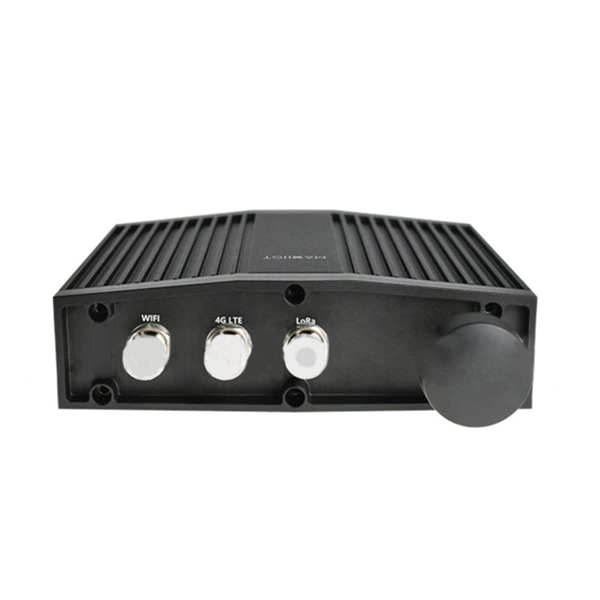
In 4G network, the optical modules used to connect BBU and RRU are mainly Gigabit to 10 Gigabit optical modules; in 5G network, the optical modules used to connect BBU and RRU are mainly 25G rate. RRU is short for remote radio unit. It also provides information about the RRU and its cables. The actual exteriors may be different. Product Versions The following table lists the product versions related to this. Can use 3. 5G rate optical module to complete the multiplexing of low-speed interface services such as 4G at a lower cost; Also used for 40KM long-distance transmission of 10G rate interface (10, 20KM for 1271nm~1371nm window). 25G SFP optical module adopts the wavelength of 850nm, with an operating. The Gamma632 is a 4G&5G dual-mode Remote Radio Unit (RRU) product independently developed by Baicells with independent intellectual property rights.
The core of a conventional optical fiber is the part of the fiber that guides the light. The core is surrounded by a medium with a lower index of refraction, typically a cladding of a different glass, or plastic. Light. A fiber optic is made of five main parts, labeled in the animation and summary image of Video 1. The numerical aperture. This post will unravel the mystery of fiber optics by exploring their three main layers— core, cladding, and coating —to show you why they're so essential for lightning-fast connections. In the 1960s, due to the advancement of technology and the growth of communication demands, people began to seek new communication technologies.
Contact us for competitive quotes on any of our power communication and smart grid products
Get a Quote