
RL (dB) is the ratio of the reflected optical power to the incident optical power at the input port of optical signals. These are known as passive optical splitters, and they perform the function. Optical splitters, encompassing FBT (Fused Biconical Taper) couplers and PLC (Planar Lightwave Circuit) splitters, are prevalent passive optical devices designed to divide fiber optic light into multiple segments based on a specified ratio. Understanding the types of splitters, their impact on network performance, and how to measure their losses ensures high-quality network operation and facilitates optimal splitter selection based on. Return loss (RL) is also called reflection loss. RL (dB) is the ratio of the reflected. By dividing a single optical signal from a central Optical Line Terminal (OLT) into multiple outputs for Optical Network Terminals (ONTs) at users' homes, splitters eliminate the need for dedicated fibers to each residence—slashing infrastructure costs while scaling network reach.
[PDF Version]
Fusion couplers, made by melting a section of twisted fibers, offer the lowest insertion loss (~0. 3 dB) and highest power handling, with a limited wavelength bandwidth of ±40 nm and polarization extinction ratio below 23 dB. Optical splitters, encompassing FBT (Fused Biconical Taper) couplers and PLC (Planar Lightwave Circuit) splitters, are prevalent passive optical devices designed to divide fiber optic light into multiple segments based on a specified ratio. T PON standards such as GPON, XGS-PON and new 25 and 50G standards. We offer a full line of fiber optic couplers and splitters supporting SM, MM, PM, large core, and double-clad fibers across 300–2000 nm, with power handling up to 100 W and operating temperatures up to 300°C. Three fabrication methods are employed: fusion, micro-optics, and planar lightwave circuit. Carrier-grade standard insert type 1-4 optical splitter, low insertion loss, uniform light splitting 2. Uniform light splitting and stable transmission using high-quality transmission.
[PDF Version]
Testing a splitter or other passive fiber optic devices like switches is little different from testing a patchcord or cable plant using the two industry standard tests, OFSTP-14 for double-ended loss (connectors on both ends) or FOTP-171 for single-ended testing. A passive device used to split or combine signals on fiber optics may be called a splitter, combiner or coupler, but splitter is the most common term. 6inch color touch screen, button/touch dual operation; Internal integration of eight major functional modules, multi-functional. As fiber deployments become commonplace, network owners and technicians are paying more attention to the two crucial devices for testing fiber optical cables: the Optical Loss Test Set (OLTS) and the Optical Time Domain Reflectometer (OTDR). An OLTS provides the most accurate insertion loss. The CertiFiber® Pro Optical Loss Test Set (OLTS) can be used to check that the loss of a PON Splitter (often referred to in various standards as a non-wavelength-selective or wavelength-selective branching device) to check that it is within the allowed defined limits. To view the full specifications, download the spec sheet below.
[PDF Version]
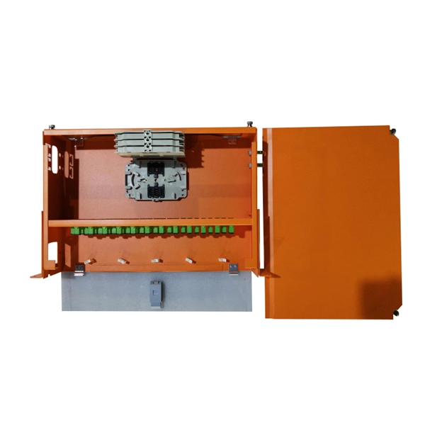
Plug-in type PLC splictter also called LGX PLC splitter used to distribute or combine optical signals in FTTH deployment. It's usually installed in the wall mount Fiber optic distribution box to save time & space and provides reliable protection for the fiber optic cores. Your browser does not. Optical fiber PLC splitter is an integrated waveguide optical power distribution device based on quartz substrate, which is especially suitable for connecting the terminal equipment in the PON network and dividing the optical information in the optical fiber communication system into multiple. Planar light-wave circuit splitter (PLC Splitter) is a type of optical power management device that is fabricated using silica optical wave-guide technology. T PON standards such as GPON, XGS-PON and new 25 and 50G standards. Ideal for FTTx and PON applications, our optical splitters ensure reliable, low-loss signal distribution for your network.
[PDF Version]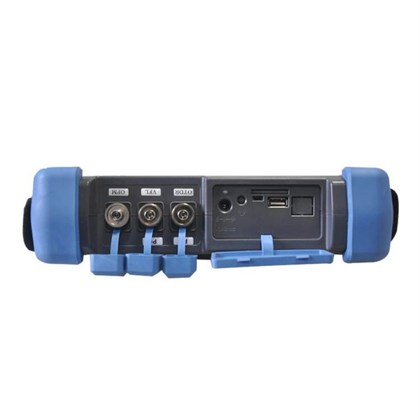
Acceptable splice loss in optical fiber is typically considered to be less than 0. The calculated loss budget is an estimate that assumes the values of component losses and does not take into account the uncertainty of the measurement. This testing will ensure that the data necessary to properly evaluate any future system malfunctions will be av nctioning. So, you drop everything and i vestigate. He's right – it is n t working. What is the typical acceptable splice loss for single-mode fiber using fusion splicing? What is the acceptable splice loss for multimode fiber using mechanical splicing? How does fiber alignment affect splice loss? Why is cleaning the fiber important before splicing? What role does the cleaver play. Splice loss refers to the part of the optical power that is not transmitted through the splice and is radiated out of the fibre. The total loss in decibels at the fusion splice is given by the following equation, where Pin is the total power incident on the fusion splice and Ptrans is the.
[PDF Version]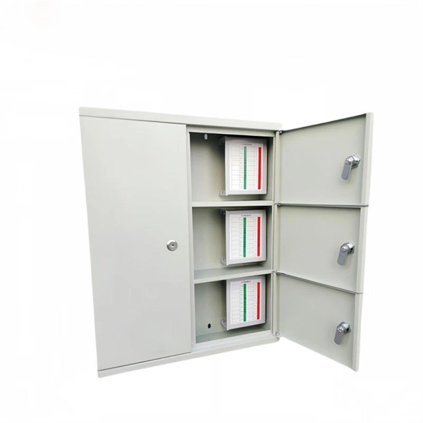
A GPON splitter is a passive optical device that takes a single fiber input and splits it into multiple outputs, typically in ratios like 1:2, 1:4, 1:8, 1:16, 1:32, and 1:64. The splitting process introduces signal attenuation, making placement strategy critical for. Gigabit Passive Optical Networks (GPON) have revolutionized fiber-optic broadband by offering high-speed connectivity to multiple users over a single fiber. A key component enabling this efficiency is the optical splitter, which divides the optical signal to serve multiple endpoints. There are no specific requirements for this document. In this guide, you'll learn how fiber splitters function in PON networks, the difference between PLC and FBT types, and how to choose the best. A fiber-optic splitter, also known as a beam splitter, is based on a quartz substrate of an integrated waveguide optical power distribution device, similar to a coaxial cable transmission system. Conversely, it can also combine multiple signals into one.
[PDF Version]Contact us for competitive quotes on any of our power communication and smart grid products
Get a Quote