
The optical receiver adds two types of noise namely thermal noise and shot noise. This application note provides an in-depth analysis of the complete receiver optical sensitivity and the potential power penalties related to the accumulation of random noise and inter-symbol interference (ISI) in both amplitude and timing. Ultimately, the noise influence on the signal will determine the system sensitivity. The challenge is to find a way to determine the. In the design of an optical receiver, it is vital that the module is capable of converting and shaping the optical signal while meeting or surpassing the maximum BER.
Fiber optic transmitters convert electrical signals into optical signals and then inject these optical signals into light- conducting cable. They use light emitting diodes (LED) or laser diodes as their optical source, and are designed for use with either single-mode or multi-mode. Optical transmitters are a crucial component in modern telecommunications, enabling the transmission of data as light signals through optical fibers. Nowadays, the applications of optical fibers mainly involve in telecommunication systems and also in the Internet & LAN (local area networks) to attain. The OPA621 is a low-noise, wide-band op amp in classical configuration, which functions as an amplifier in the I/V conversion section behind the photodiode and as an I/V converter behind the AGC multiplier. Essentially, they act as the starting point for a fiber optic.
The formula is simple: sum the cross-sectional areas of all cables inside the conduit, divide by the conduit's inner area, multiply by 100. Use this calculator to estimate total optical attenuation across your network and confirm system performance against recommended design margins. The tool accounts for fiber attenuation, connector and splice losses, splitters, and other passive components, helping ensure reliable transmission in. A tool that computes how many fibers fit in a circular bundle and splits them into user-defined segments for cable-assembly planning. Key Parameters: • Center Diameter, Fiber Diameter, Packing Efficiency, Section Count Calculation: Visualization: • Color-coded radial diagram with per-section. Fill ratio — sometimes called fill percentage — is the ratio of the total cross-sectional area occupied by cables to the interior cross-sectional area of the conduit, expressed as a percentage.
[PDF Version]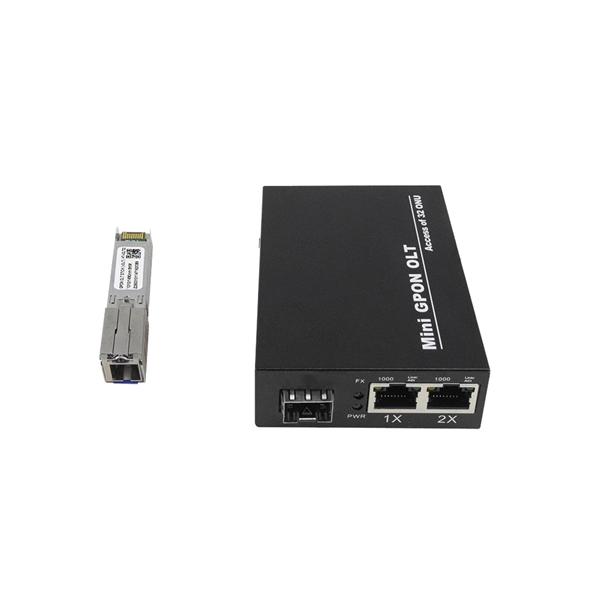
Q: How can receiver sensitivity be optimized? A: Receiver sensitivity can be optimized by employing techniques such as noise reduction, amplification, and signal processing, as well as careful detector selection and amplifier design. Optimizing SNR is all about tipping the balance in favor of the signal you want, so noise doesn't drown it out. That's the key to reliable communication and measurement. In essence, it measures how well a receiver can detect weak optical signals. amplitude shift keying (ASK) or on off keying (OOK). Voltage level is switched between two values, which are usually on and off.
Synchronous Optical Networking (SONET) and Synchronous Digital Hierarchy (SDH) are standardized protocols that transfer multiple digital bit streams synchronously over optical fiber using lasers or highly coherent light from light-emitting diodes (LEDs). We demonstrate a switching contrast of 31. 9 dB, corresponding to a propagation distance of 14 mm, achieved by launching temporally synchronized SP-CP pairs into the fast core of the DCF with moderate inte -core asymmetry. It provides an expert-curated supplier directory, buyer-focused technical background information, and structured selection criteria to support professional procurement decisions. At low transmission rates, data can also be. Com-pared with weakly-coupled MCFs with independent cores, it can simultaneously realize higher spatial channel density and ultralow transmission loss using existing ultralow-loss single-mode fiber (SMF) core designs.
[PDF Version]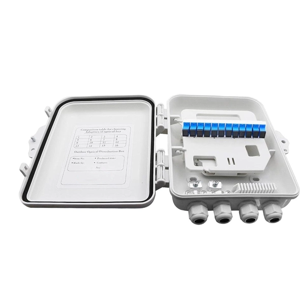
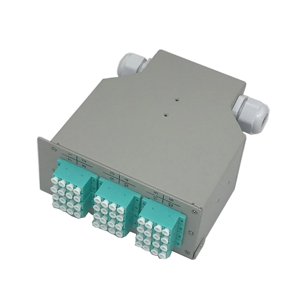
By dividing a single optical signal from a central Optical Line Terminal (OLT) into multiple outputs for Optical Network Terminals (ONTs) at users' homes, splitters eliminate the need for dedicated fibers to each residence—slashing infrastructure costs while scaling network reach. In this guide, we'll break down what fiber splitters do, how they work, and. An Optical Splitter, also known as a beam splitter, is a passive optical device that divides a single input optical signal into two or more output signals. Conversely, it can also combine multiple signals into one. Imagine you have a single fiber cable bringing blazing-fast internet to your home or office, but you want to connect multiple. Yes, a fiber splitter can be used for home networking, but its applicability depends on several factors.
For instance, a 1:8 splitter ratio signifies an equal distribution of incoming optical power among eight output ports, with each port receiving 1/8th of the total power. Common splitters include 1x2 fiber. Cost Efficiency: A single OLT port can serve 8–64 ONTs via a splitter, reducing the number of OLTs, fibers, and deployment labor needed. Passive Operation: Splitters have no active electronics, so they require no power, cooling, or maintenance—lowering operational costs (OPEX) for ISPs. While 1:n or 2:n couplers are most common, there are n:n couplers also, e. These devices are generally bidirectional. With a 1:n device, in one. In fiber optic networks, particularly in FTTx (Fiber to the x) and PON (Passive Optical Networks) deployments, splitters play a central role in distributing the optical signal from a single source to multiple destinations. In this article, we'll explain the concept of split.
[PDF Version]
A simple solution is to combine a Corning USB “A to receptacle-A” USB 3. Optical™ Cables by Corning with a short, off-the-shelf jumper cable that has a USB “A” plug on one side and the particular connector your end device requires on the other. 0 A female port of the AOC Cable. Vielen Dank für den Kauf dieses Optischen USB 3. Es unterstützt größere Distanzen als herkömmliche Kupferkabel, ist deutlich flexibler und leichter und daher optimal. A workaround would be to connect the USB 3. Once connected, check the Windows Device Manager to verify the devices that have been successfully connected through the device. The USB active optical cables are designed to be compliant with SuperSpeed USB and SuperSpeed+ USB electrical specifications, offering seamless interoperability between existing USB 3. 1 hosts, hubs and devices, ensuring a trouble-free plug-and-play experience. The USB AOC address the. Connect the USC-CC32 Type C device connector to the USB Hub.
[PDF Version]
Passive optical networking (PON), like active optical networking, uses fiber-optic cabling to provide Ethernet connectivity from a main data source to endpoints. In practice, PONs are typically used for the last mile between Internet service providers (ISP) and their customers. It uses only optical fibers to transmit data, voice, and video services. A PON network consists exclusively of passive optical components. "Passive" refers to the use of optical fiber cables connected to an unpowered splitter, which in turn transmits data from a service. In a PON access network there are two end-points with active (powered) electronic transmission equipment, connected by passive (non-powered) equipment known as outside fiber plant.
Contact us for competitive quotes on any of our power communication and smart grid products
Get a Quote